
Current source sine wave voltage driving circuit via voltage-clamping and soft-switching techniques
Patent Information
- Authority / Receiving Office
- US · United States
- Current Assignee / Owner
- Publication Date
- 2005-12-15
- Estimated Expiration
- Not applicable · inactive patent
Smart Images
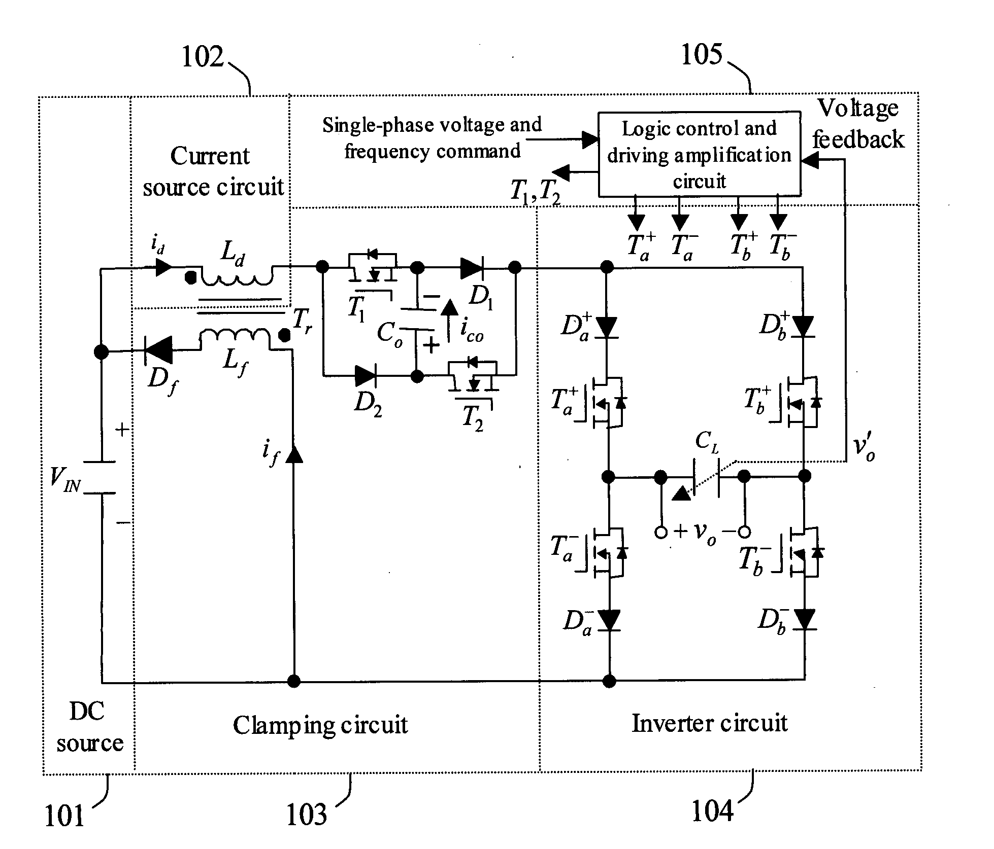
Figure 1 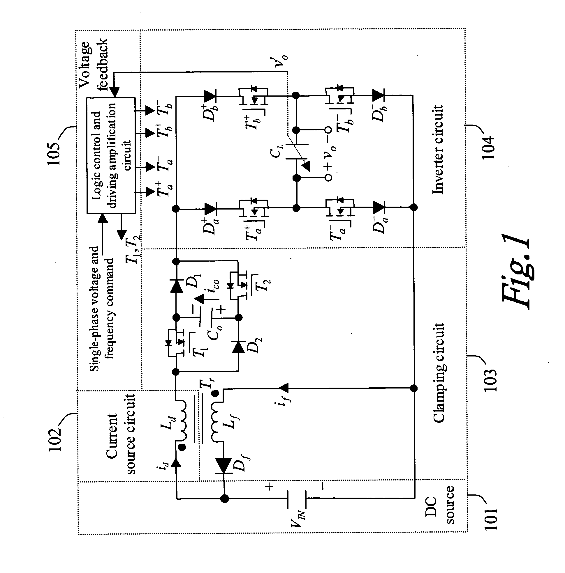
Figure 2 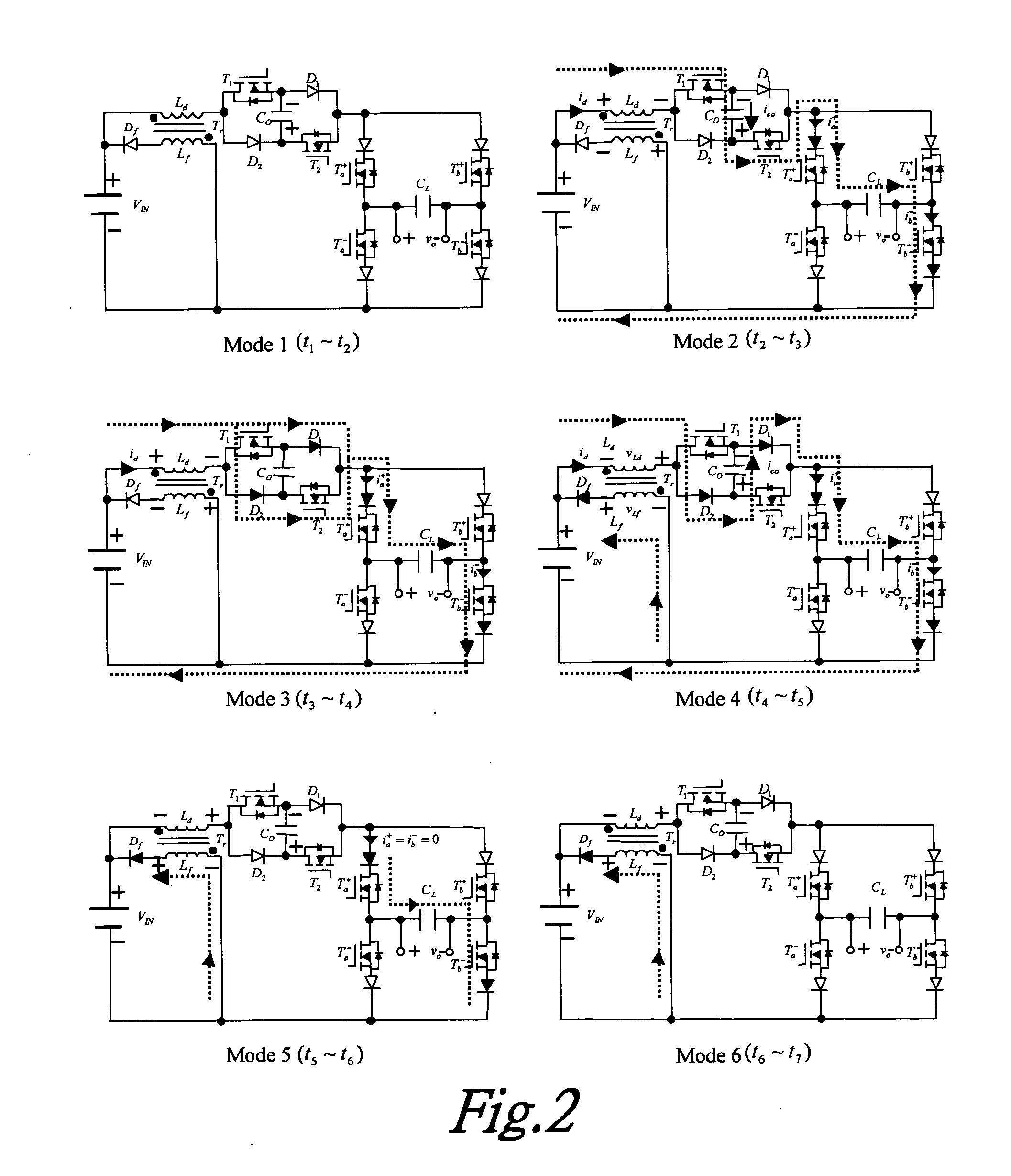
Figure 3
Abstract
Description
BACKGROUND OF THE INVENTION
[0001] 1. Field of the Invention
[0002] The present invention relates to a current-source sine wave voltage driving circuit using voltage-clamping and soft-switching techniques, more particularly it relates to a current-source sine wave voltage driving circuit using voltage-clamping and soft-switching techniques, which converts a DC source to an AC sine wave voltage using the difference between the AC sine wave voltage command and the feedback voltage to control the turn-on time of switches, and using an inductor to generate a current source to charge capacitors via positive / negative cycles of full-bridge switch to adjust a rise and fall range of voltage to provide linear voltage regulation.
[0003] 2. Description of the Prior Art
[0004] Presently there are two kinds of products which can convert a DC source to 60 Hz AC voltage: one is inverter of AC motor, which uses coil inductor of motor and PWM (pulse width modulation) technique to generate sine-wave-l...
Examples
Embodiment Construction
[0028]FIG. 1 illustrates a block diagram of the current-source sine wave voltage driving circuit using voltage-clamping and soft-switching techniques. When the output voltage is at the upper half cycle of the sine wave, current flows from DC source 101 through inductor Ld of the current source circuit 102 and switches T1, T2 of the clamping circuit 103, then via switches Ta+, Tb− of the inverter circuit 104 to charge the output capacitor CL. Similarly, when the output voltage is at the lower half cycle of the sine wave, switches T1, T2, Ta+, Ta− turn on at the same time to discharge the output capacitor CL. The inductor Ld of the current source circuit 102 is placed among voltage sources VIN, VCo and Vo, to limit the current value, the ascending rate of the inductor current being proportional to voltage applied to the inductor. The symbol Ld and Lf are primary side and secondary side of a transformer with high exciting current, respectively.
[0029] There are four purposes to the cla...