
Coil device
Patent Information
- Authority / Receiving Office
- US · United States
- Current Assignee / Owner
- Publication Date
- 2007-03-22
Smart Images
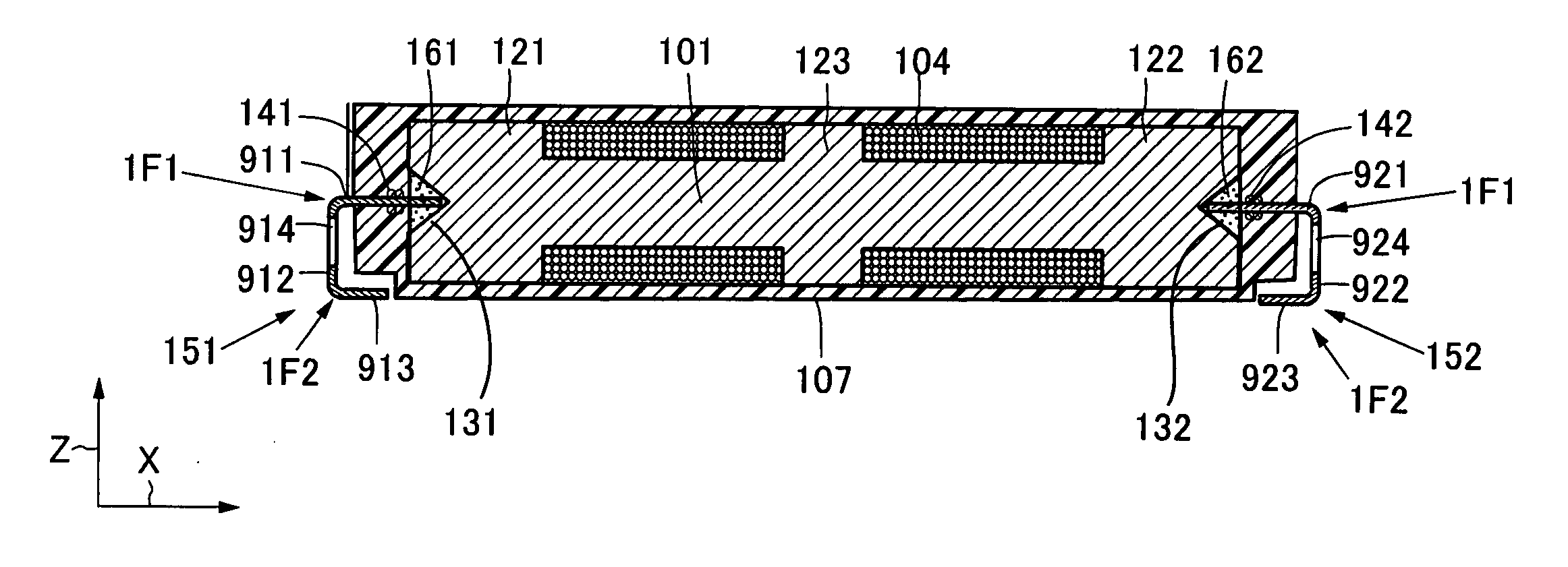
Figure 1 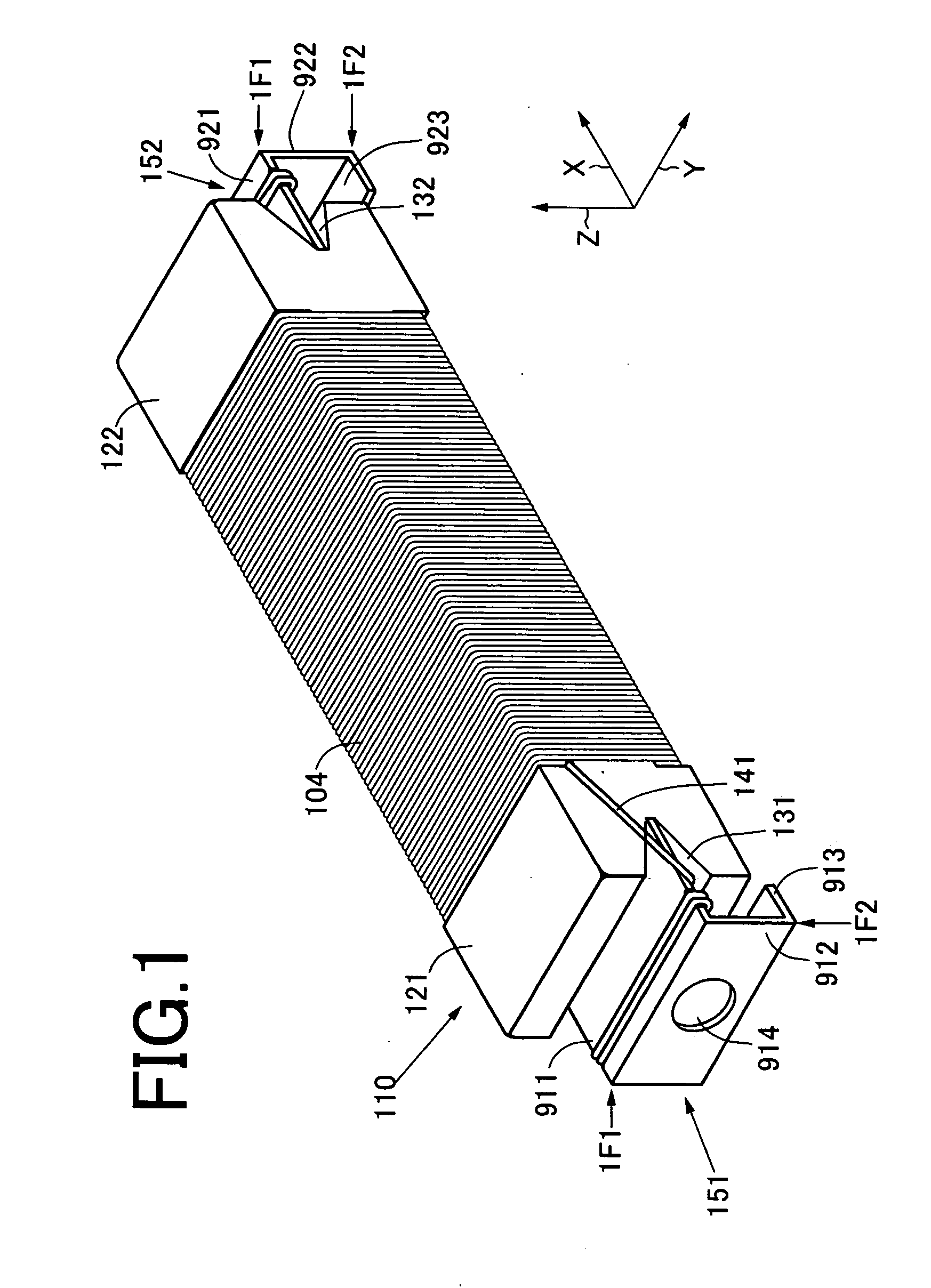
Figure 2 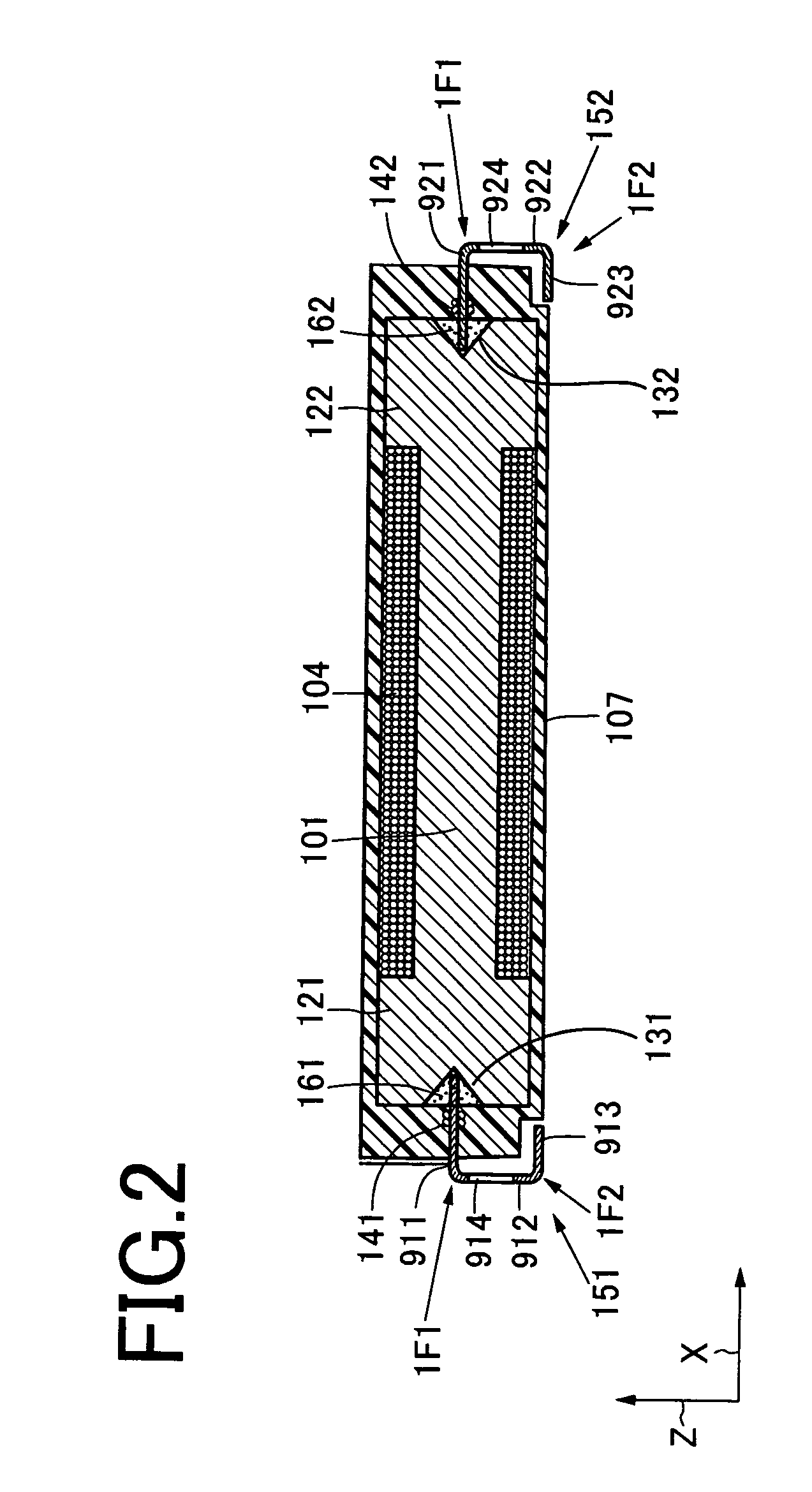
Figure 3
Abstract
Description
TECHNICAL FIELD
[0001] The present invention relates to a ferrite core and a coil apparatus using this ferrite core.
[0002] A coil apparatus according to the present invention includes an antenna which is applicable to an in-vehicle transponder, or a communication device inductor, a choke coil and others. BACKGROUND ART
[0003] Various types of coil apparatuses have been conventionally proposed and come into practical use. As one of such apparatuses, a coil apparatus which can be applied as an in-vehicle antenna or a transponder has been recently proposed. In the coil apparatus which is applied to such an intended purpose, a ferrite core having excellent high-frequency characteristics is generally used. Further, a coil is wound around this ferrite core for the necessary number of times, and a coil end is connected with metal terminals provided at both ends of the ferrite core in a longitudinal direction so that an entire structure is covered with a thermosetting resin such as an epox...
Examples
first embodiment
of the Invention
[0113]FIG. 1 is a perspective view of a coil apparatus according to another embodiment of the present invention, FIG. 2 is a front cross-sectional view of the coil apparatus depicted in FIG. 1, and FIG. 3 is a perspective view showing a terminal used in the coil apparatus depicted in FIGS. 1 and 2. This coil apparatus can be used in, e.g., an antenna, an in-vehicle antenna, a transponder, a choke coil, an inductor of an electronic device and others.
[0114] Referring to FIGS. 1 and 2, the coil apparatus includes a core 110, a winding 104 and terminals 151 and 152 and further comprises an insulating resin 107.
[0115] The core 110 has terminal attachment portions 121 and 122 at opposed both ends thereof, and has a winding portion 101 in an intermediate portion thereof. The core 110 is typically a ferrite core, and its material is selected in accordance with requested characteristics. The ferrite core can be obtained from a sintered body of ferrite particles or by mechan...
second embodiment
of the Invention
[0146] A second embodiment of the present invention will now be described with reference to the accompanying drawings. It is to be noted that like reference numerals denote like or corresponding parts in the drawings.
[0147]FIG. 12 shows a vertical cross section of a coil apparatus according to a further embodiment of the present invention. A coil apparatus 201 mainly comprises a ferrite core 203, a coil 205, an insulating sheath body 207 and a pair of terminals 209 and 211. Moreover, the coil apparatus 201 is applied to, e.g., a bi-directional keyless entry system which requires no button operation, an antitheft immobilizer, a tire air pressure monitoring system in an automobile.
[0148] The coil 205 is formed of a winding which is wound on an outer peripheral surface of the ferrite core 203 with the ferrite core 203 at the center. The insulating sheath body 207 is provided to cover the entire surfaces of the ferrite core 203 and the coil 205.
[0149] As shown in FIGS...
third embodiment
of the Invention
[0176] A third embodiment according to the present invention will now be described with reference to the accompanying drawings.
[0177]FIG. 16 is a cross-sectional view of a coil apparatus according to a still further embodiment of the present invention. FIG. 17 is a perspective view showing a state before each terminal is bent in the coil apparatus depicted in FIG. 16. The coil apparatus of the illustrated embodiment can be used in an antenna, an in-vehicle antenna, a transponder, an inductor for an electronic device or the like. The illustrated coil apparatus includes a core 301, a coil 304, two terminals 351 and 352 and an insulating covering body 307.
[0178] The core 301 includes a coil winding portion 311 and two flange portions 321 and 322. The core 301 in the illustrated embodiment is formed of ferrite, and can be obtained from a sintered body of ferrite particles, by machining processing of a ferrite rod material or by combining the sintered body with machinin...