
Steep-taper flared stents and apparatus and methods for delivering them
a technology of stents and taper plates, which is applied in the field of stents, can solve problems such as improper deployment and achieve the effects of enhancing the support of the ostium, sufficient stiffness, and reducing the risk of improper deploymen
Patent Information
- Authority / Receiving Office
- US · United States
- Patent Type
- Applications(United States)
- Current Assignee / Owner
- Publication Date
- 2007-03-22
Smart Images
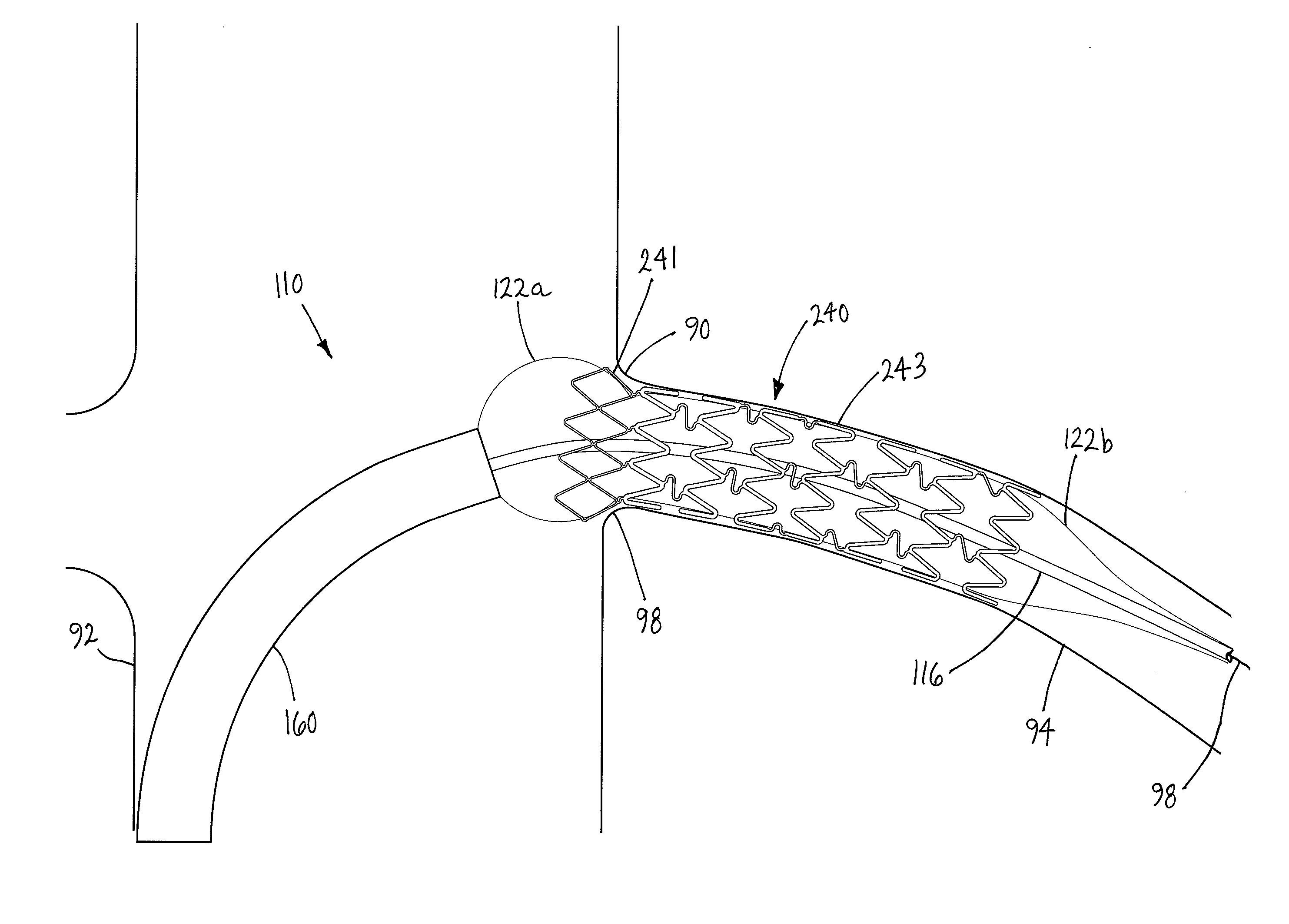
Figure 1 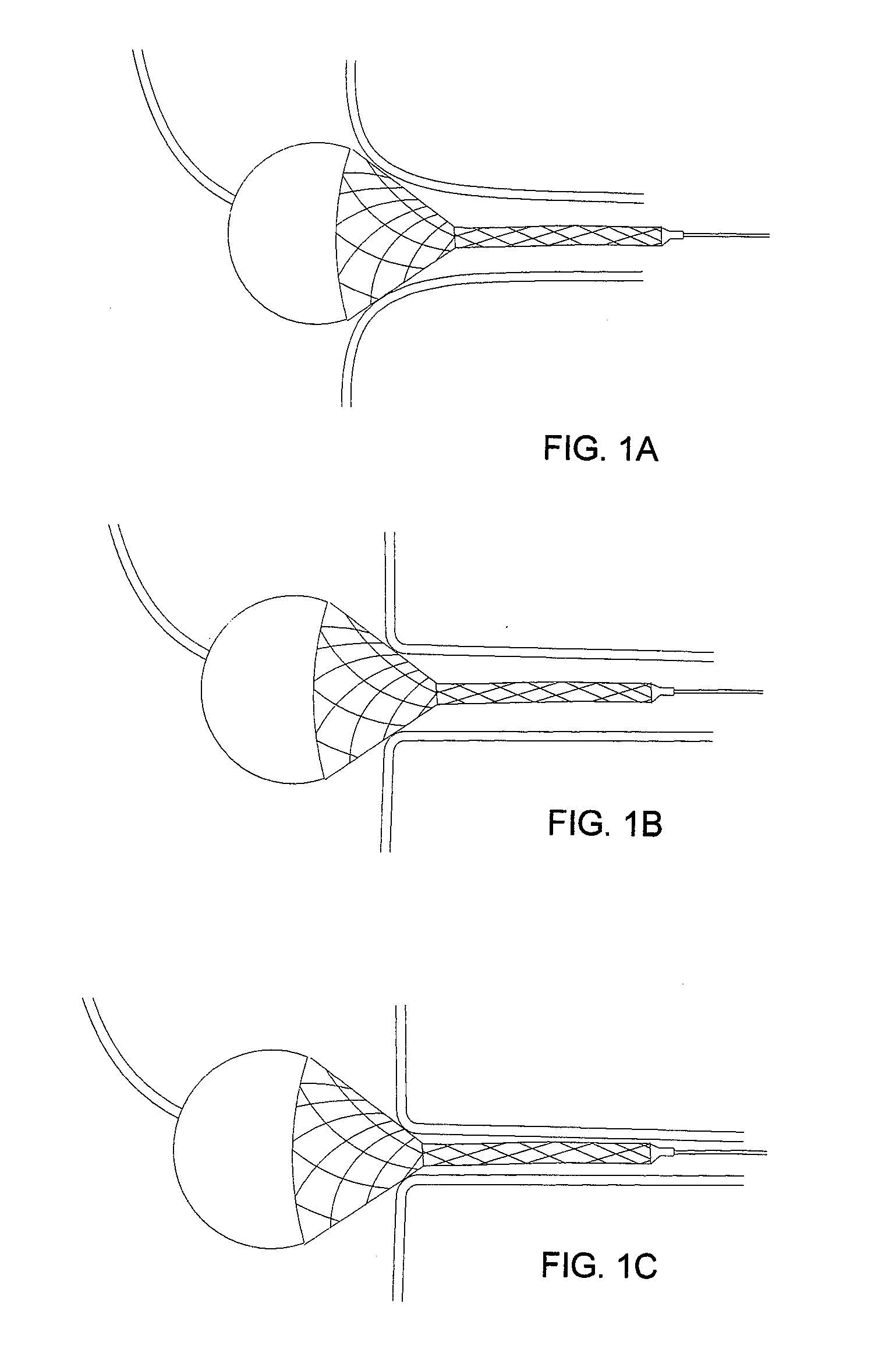
Figure 2 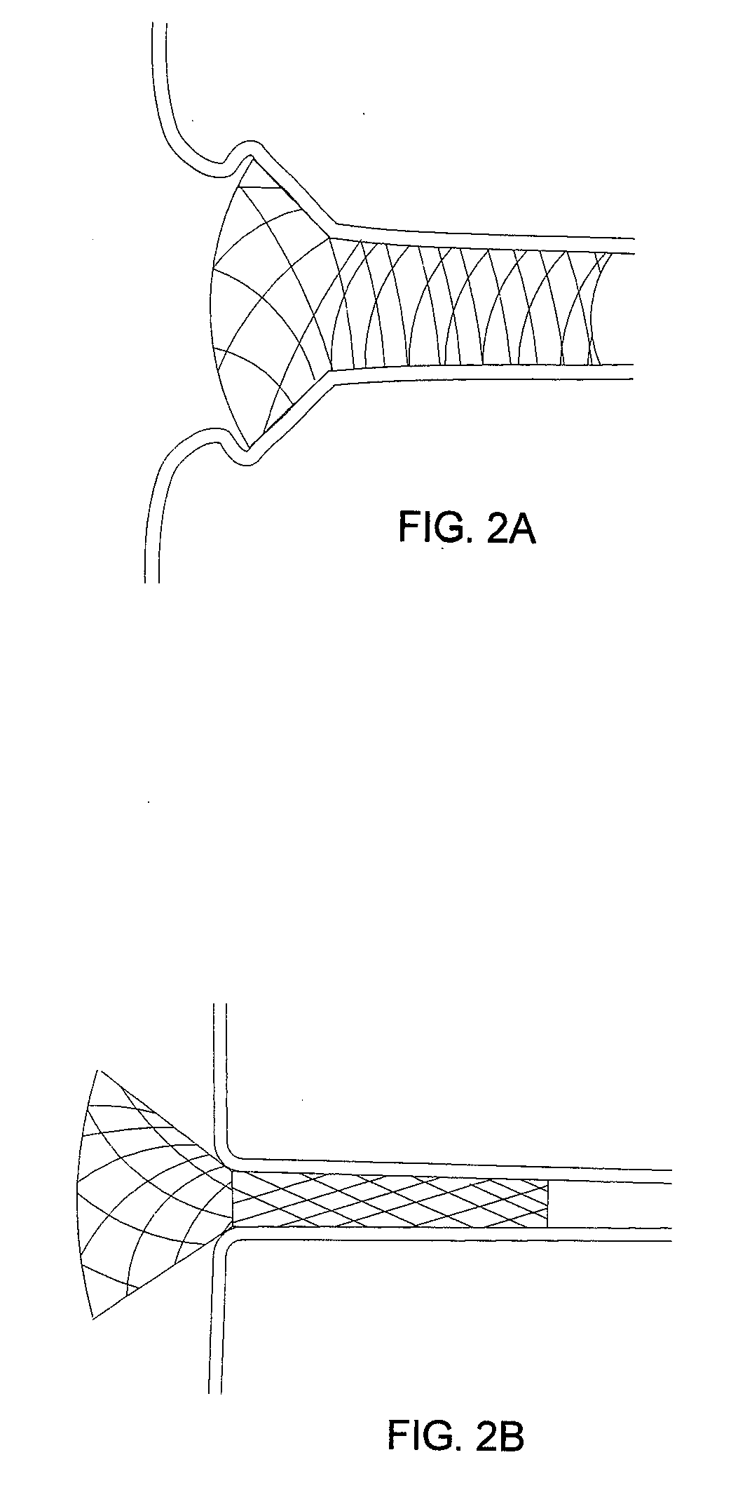
Figure 3
Abstract
Description
[0001] This application claims benefit of provisional applications Ser. Nos. 60 / 710,521, filed Aug. 22, 2005, 60 / 727,703, filed Oct. 17, 2005, 60 / 757,600, filed Jan. 9, 2006, 60 / 743,880, filed Mar. 28, 2006, and 60 / 745,177, filed Apr. 19, 2006, the entire disclosures of which are expressly incorporated by reference herein.FIELD OF THE INVENTON
[0002] The present invention relates generally to endoluminal prostheses or “stents,” and, more particularly, to flared stents, and to apparatus and methods for delivering such stents into an ostium of a blood vessel or other body lumen. BACKGROUND
[0003] Tubular endoprosthesis or “stents” have been suggested for dilating or otherwise treating stenoses, occlusions, and / or other lesions within a patient's vasculature or other body lumens. For example, a self-expanding stent may be maintained on a catheter in a contracted condition, e.g., by an overlying sheath or other constraint, and delivered into a target location, e.g., a stenosis within a ...
Examples
Embodiment Construction
[0069] Turning to the drawings, FIGS. 4-6 show exemplary embodiments of a stent 40 that includes a generally cylindrical tubular member including a proximal or first end 42 and a distal or second end 44 defining a longitudinal axis 46 therebetween. The stent 40 is generally radially expandable from a contracted or delivery condition (not shown), to a flared condition (e.g., as shown in FIGS. 5A, 6A, and 6C), and to an enlarged or fully deployed condition (e.g., as shown in FIGS. 5B, and 6B-6E). For example, the stent 40 may include a first end portion 41 at the first end 42 and a second portion 43 adjacent the first end portion 41, and a plurality of connectors 10 connecting the second portion 43 to the first end portion 41.
[0070] In an exemplary embodiment, the stent 40 may include a plurality of annular bands of cells 47-49 disposed between the proximal and distal ends 42, 44. Each band of cells 47-49 may be defined by a plurality of struts or other elements extending axially alo...