
Method of speckle size and distribution control and the optical system using the same
Patent Information
- Authority / Receiving Office
- US · United States
- Current Assignee / Owner
- Publication Date
- 2008-07-24
- Estimated Expiration
- Not applicable · inactive patent
Smart Images

Figure 1 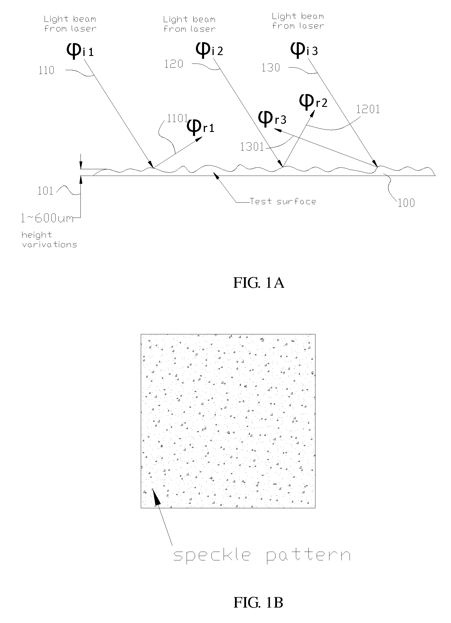
Figure 2 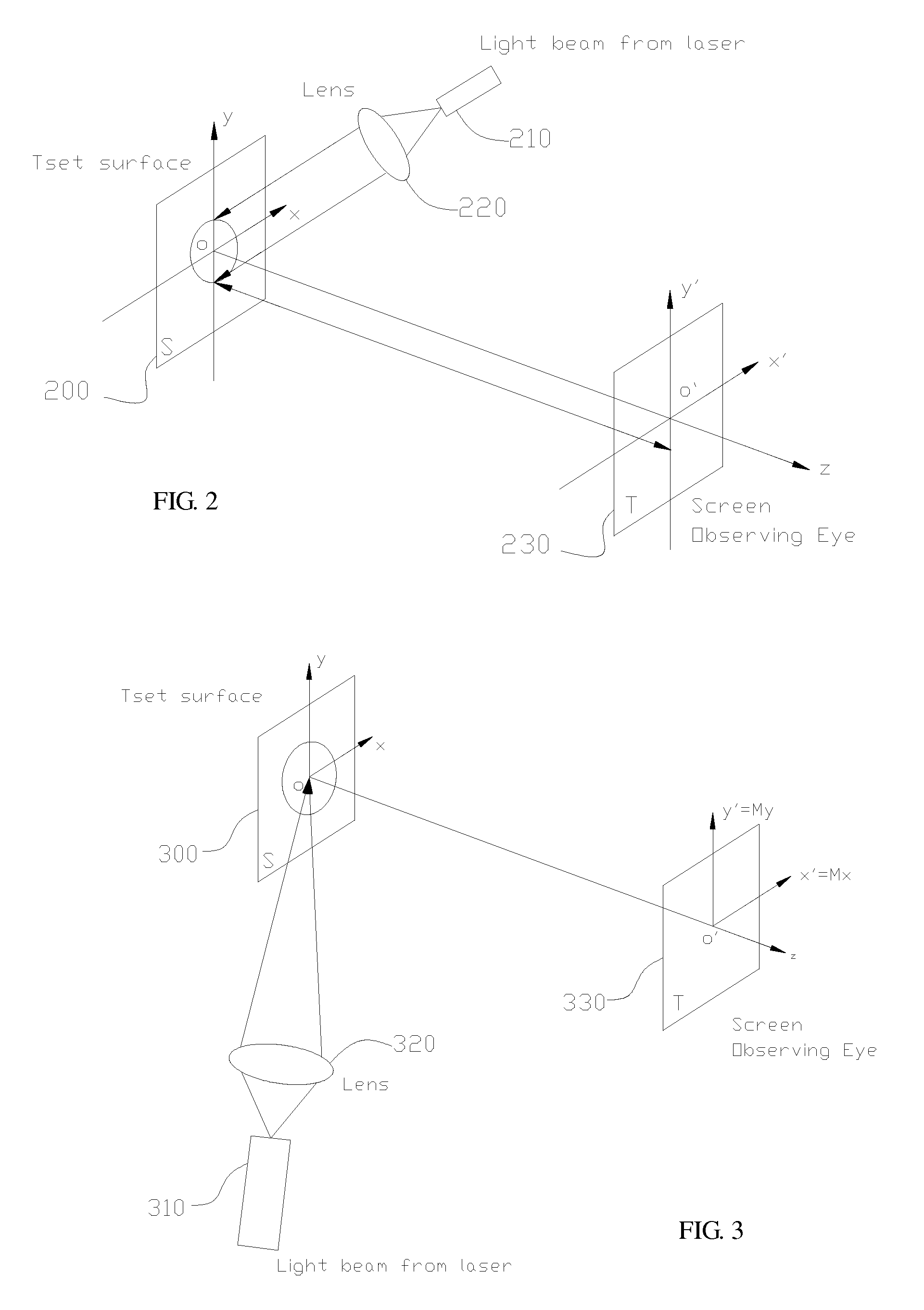
Figure 3
Abstract
Description
FIELD OF THE INVENTION
[0001] The present invention relates to a method of speckle size and distribution control and the optical system using the same, and more particularly, to an optical system which uses a laser unit and a lens set designed specifically for the laser unit instead of the conventional LED unit and its lens set with light collimation ability as its light source so as to controls the speckle sizes and the speckle pattern distribution by adjusting the bandwidth of a coherent laser beam being emitted out of the laser unit as well as by adjusting the distance between an image plane of the digital signal processing unit and the rough surface being illuminated by the coherent laser beam, by which the distribution of the resulting speckle pattern and the size of each speckle thereof can match with the effective pixel size of different image sensing units used in the optical system. The method and optical system is advantageous in its simple optical path, by which the mechani...
Examples
Embodiment Construction
[0058]For your esteemed members of reviewing committee to further understand and recognize the fulfilled functions and structural characteristics of the invention, several preferable embodiments cooperating with detailed description are presented as the follows.
[0059]Please refer to FIG. 14 to FIG. 18 and FIG. 20, which show respectively various optical system and their methods of speckle size and distribution control, As seen in FIG. 20, an optical system is arranged inside a housing 2020 of a laser computer mouse. Preferably, the optical system 2020 is primarily composed of: a laser device 1410 (or 1510, or 1610, or 1710, or 1810), a lens set 1420 (or 1520, or 1620, or 1720, or 1820) and an imaging device 1430 (or 1530, or 1630, or 1730, or 1830), as seen in FIG. 14 (or in FIG. 15, or in FIG. 16, or in FIG. 17, or in FIG. 18), in which the laser device 1410 (or 1510, or 1610, or 1710, or 1810) is used as a light source for providing a laser beam to the optical system 2020; the len...