
Gas purification apparatus and method for gas purification
Patent Information
- Authority / Receiving Office
- US · United States
- Current Assignee / Owner
- Publication Date
- 2009-06-18
Smart Images
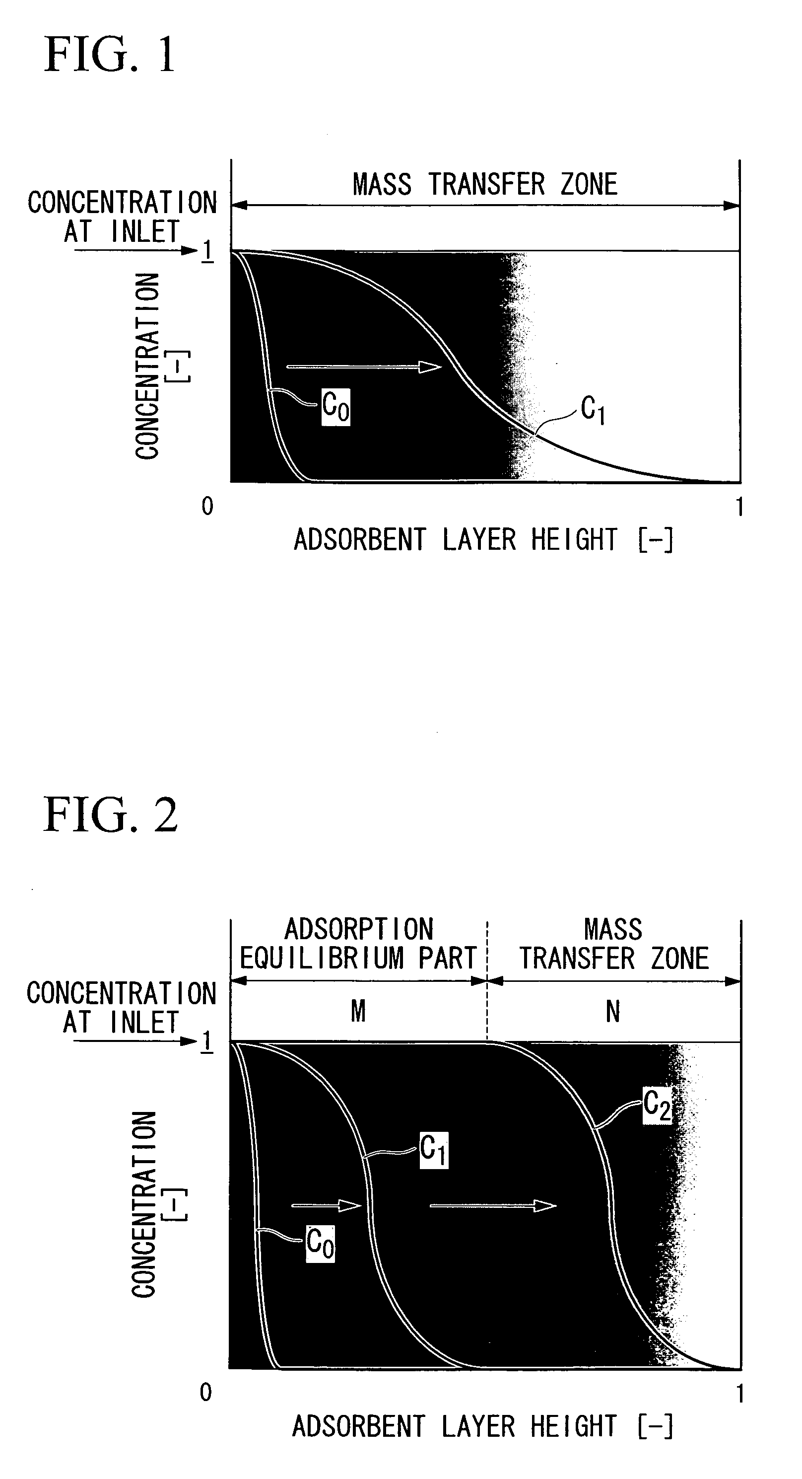
Figure 1
Abstract
Description
TECHNICAL FIELD
[0001] The present invention relates to a gas purifier which removes impurities contained in a gas such as carbon dioxide contained in air or carbon monoxide contained in high purity nitrogen, and to a method for gas purification using the same. In particular, the present invention relates to a gas purifier and a method for gas purification which are suitable for removing carbon dioxide in feed air in cryogenic air separation. Moreover, the present invention enables a gas purifier to be downsized.
[0002] Priority is claimed on Japanese Patent Application No. 2005-185725, filed Jun. 24, 2005, the contents of which are incorporated herein by reference.BACKGROUND ART
[0003] In cryogenic air separation, unnecessary components such as moisture, carbon dioxide, a nitrogen oxide, or a hydrocarbon in feed air are previously removed, and then cryogenic air separation is performed. Recently, an adsorption method is used for this removal of unnecessary components.
[0004] This adsorptio...
Examples
first embodiment
[0056]First, an embodiment of the present invention, in which carbon dioxide in air is removed by an adsorbent, is described in detail.
[0057]In the present invention, a gas-purifying agent layer refers to a layer formed by packing a gas-purifying agent in a purifier. Also, an adsorbent is a type of a purifying agent, and the term of an adsorbent layer refers to a layer formed by packing an adsorbent in a purifier.
[0058]FIG. 1 schematically represents the concept until a constant pattern of concentration distribution of impurities in the present embodiment is formed. In FIG. 1, the vertical axis represents a relative concentration of carbon dioxide in feed air. Also, the horizontal axis represents the packed height of an adsorbent layer which is normalized to be dimensionless. The point zero on the horizontal axis is the inlet of air, and the point 1 is the outlet of purified air.
[0059]When an adsorption step is started, feed air is fed into an adsorbent layer from the left side of F...
second embodiment
[0090]Next, an embodiment in which carbon monoxide in high purity nitrogen is removed by using, as a gas-purifying agent, a reactant formed of an inorganic porous substance in which nickel metal is supported.
[0091]This reactant is reacted with a trace amount of carbon monoxide and converted into metal carbonyl, and thereby carbon monoxide can be removed. The regeneration of the reactant is performed by allowing it in a heated state and flowing hydrogen so as to reduce it.
[0092]Therefore, at least two purification columns, in which the aforementioned reactant is packed, are provided and operated while alternately switching between a removal step and a regeneration step, and thereby carbon monoxide in high purity nitrogen can be continuously removed.
[0093]In this removal operation, conventionally, purification columns filled with a large amount of reactant are used, and the switching time is set long, such as 2 to 3 days. In this conventional method, a large amount of reactant has to ...
example 1
[0100]Here is a description of the case of purifying air having a feed air pressure: 550 kPa (absolute pressure), an air temperature: 10° C., an air flow rate: 30,000 Nm3 / hour, and a carbon dioxide content: 400 ppm (volume).
[0101]In equation (1), in the case of α=1.04, T=2 hours, u=0.33 m / s, and q=1.33 mol / kg, the result became H≧0.52 m.
[0102]Here, when the first aspect of the present invention was examined, the load of carbon dioxide flowing into an adsorbent layer in the purification step became as follows.
Load=30000 [m3 / hour]×400 [ppm]×10−6×2 [hour]÷0.0224 [Nm3 / mol]=1072 [mol]
Column diameter=(30000 [N m3 / hour]×101 [kPa]÷550 [kPa]×283 [K]÷273 [K]×4÷π÷0.33 [m / s]+3600 [s / hour])0.5=2.47 [m]
[0103]When an adsorbent having a packed density of 650 kg / m3 was used, the adsorption capacity possessed by half of the amount of an adsorbent was as follows.
Adsorption capacity possessed by half of amount of adsorbent=2.472×π÷4×0.52×650×1.33÷2=1077 [mol]
[0104]Accordingly, adsorption capacity posse...