
Filtering unit and relative filtering cartridge
a filtering unit and cartridge technology, applied in the direction of stationary filtering element filters, dispersed particle filtration, liquid separation agents, etc., can solve the problems of increasing the production cost of the filtering cartridge and the casing, not easy to decouple in an equally quick and easy manner, and the bayonet-like couplings reveal some drawbacks
Patent Information
- Authority / Receiving Office
- US · United States
- Current Assignee / Owner
- Publication Date
- 2014-06-05
Smart Images
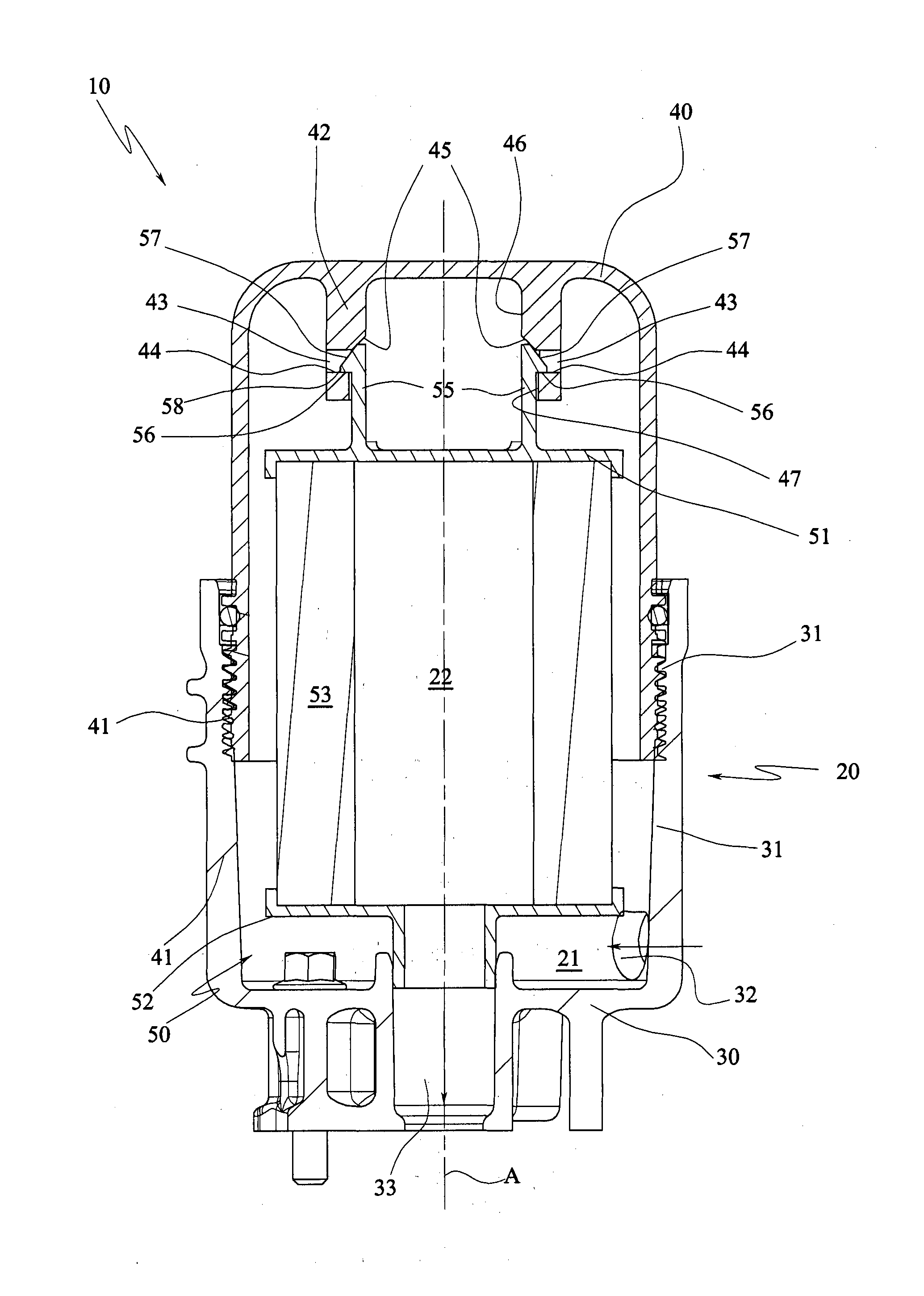
Figure 1 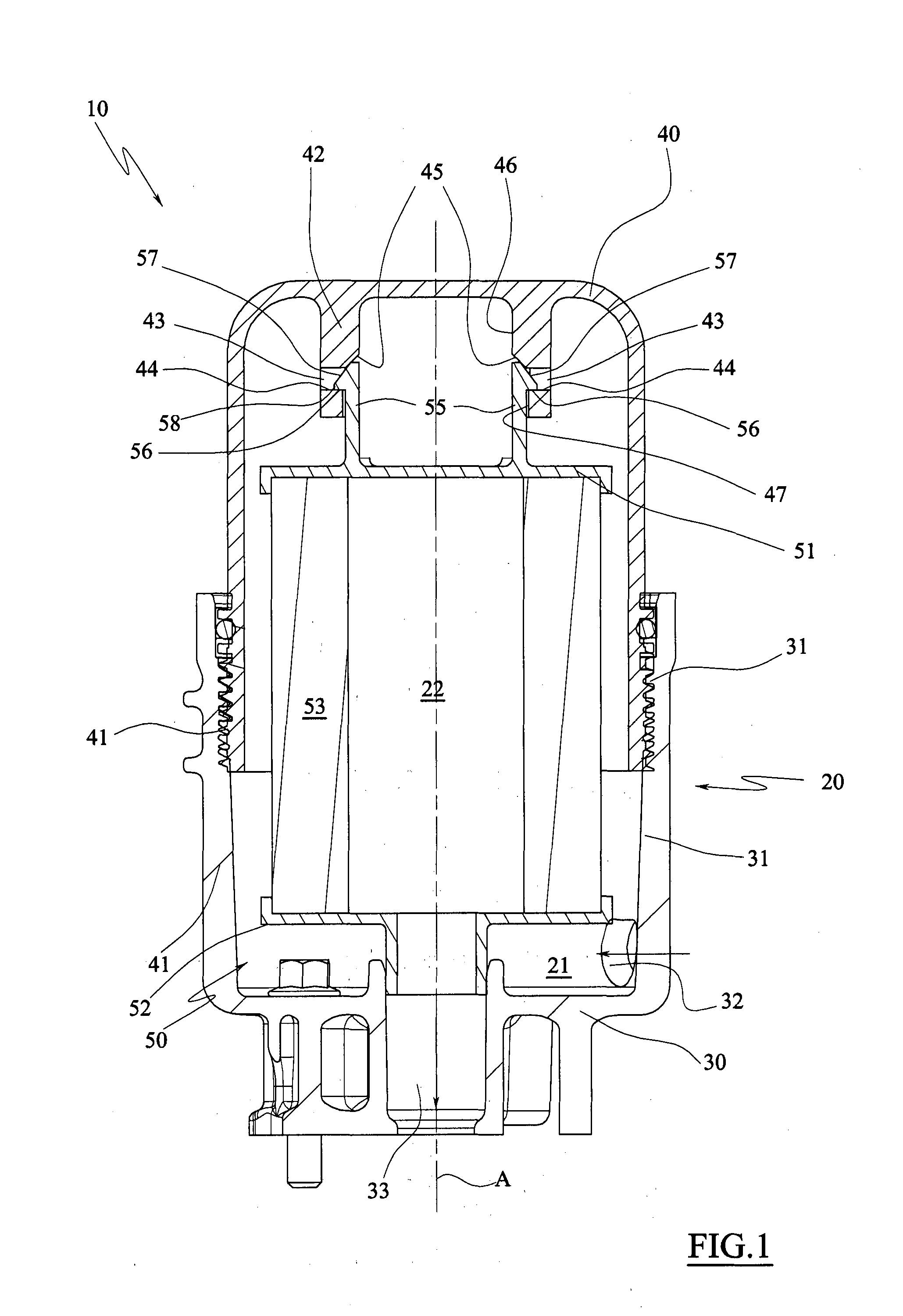
Figure 2 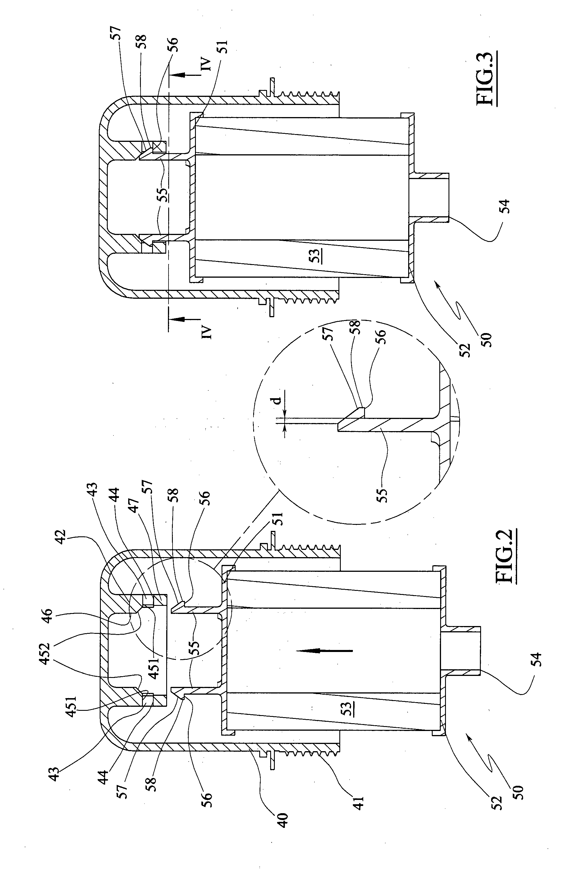
Figure 3
Abstract
Description
FIELD OF THE INVENTION
[0001] The present invention regards a filtering unit and the relative filtering cartridge.
[0002] Mainly the invention regards a unit for filtering lubricant oil, air or fuel in automotive applications, more in particular in applications in which there is required a high flow rate of such fluids from the filter, such as for example trucks, buses, commercial vehicles and work machines or where there is required a medium fluid flow rate, like in the motor vehicle industry.PRIOR ART
[0003] As known the filtering of lubricant fluids in the automotive industry is generally obtained by means of a filtering unit comprising an external casing provided with an inlet for the fluid to be filtered and an outlet for the filtered fluid, and a filtering cartridge adapted to define a chamber, internal or external, communicating with the inlet of the fluid to be filtered.
[0004] Thus, the fluid flowing from the inlet towards the outlet of the filter is forced to traverse the filterin...
Examples
first embodiment
[0031]FIG. 2 is a longitudinal sectional view of a filtering cartridge in a first position before coupling to the support body obtained in the cover of the casing, according to the filtering unit, and the relative enlarged detail.
[0032]FIG. 3 is a view of FIG. 2 with the filtering cartridge in coupled position.
[0033]FIG. 4 is the view along the line of section IV-IV of FIG. 3.
[0034]FIG. 5 is a longitudinal sectional view of the filtering cartridge of FIG. 2 in a first decoupling position.
[0035]FIG. 6 is the view along the line of section VI-VI of FIG. 5.
[0036]FIG. 7 is a longitudinal sectional view of the filtering cartridge of FIG. 2 in a second decoupling position.
[0037]FIG. 8 is the view along the line of section VIII-VIII of FIG. 7.
[0038]FIG. 9 is a longitudinal sectional view of the filtering cartridge of FIG. 2 in a decoupled configuration.
second embodiment
[0039]FIG. 10 is a longitudinal sectional view of the filtering cartridge in a first position before coupling to the cover, according to the filtering unit, and the relative enlarged detail.
[0040]FIG. 11 is a view of FIG. 10 with the filtering cartridge in a coupled position.
[0041]FIG. 12 is the view along the line of section XII-XII of FIG. 11.
[0042]FIG. 13 is a longitudinal sectional view of the filtering cartridge of FIG. 10 in a first de coupling position.
[0043]FIG. 14 is the view along the line of section XIV-XIV of FIG. 13.
[0044]FIG. 15 is a longitudinal sectional view of the filtering cartridge of FIG. 10 in a second decoupling position.
[0045]FIG. 16 is the view along the line of section XVI-XVI of FIG. 15.
[0046]FIG. 17 is a longitudinal sectional view of the filtering cartridge of FIG. 10 in a decoupled configuration.
[0047]FIG. 18 is a view of a detail regarding the coupling element of FIG. 17.