
Electromagnetic relay
a technology of electromagnetic relays and relays, applied in relays, emergency protective arrangements for limiting excess voltage/current, circuit-breaking switches, etc., can solve problems such as difficulty in performing arc-extinction
Patent Information
- Authority / Receiving Office
- US · United States
- Patent Type
- Applications(United States)
- Current Assignee / Owner
- Publication Date
- 2010-11-18
Smart Images
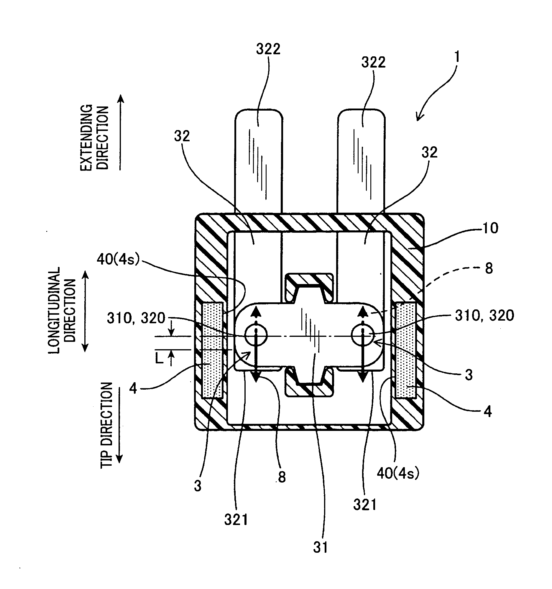
Figure 1 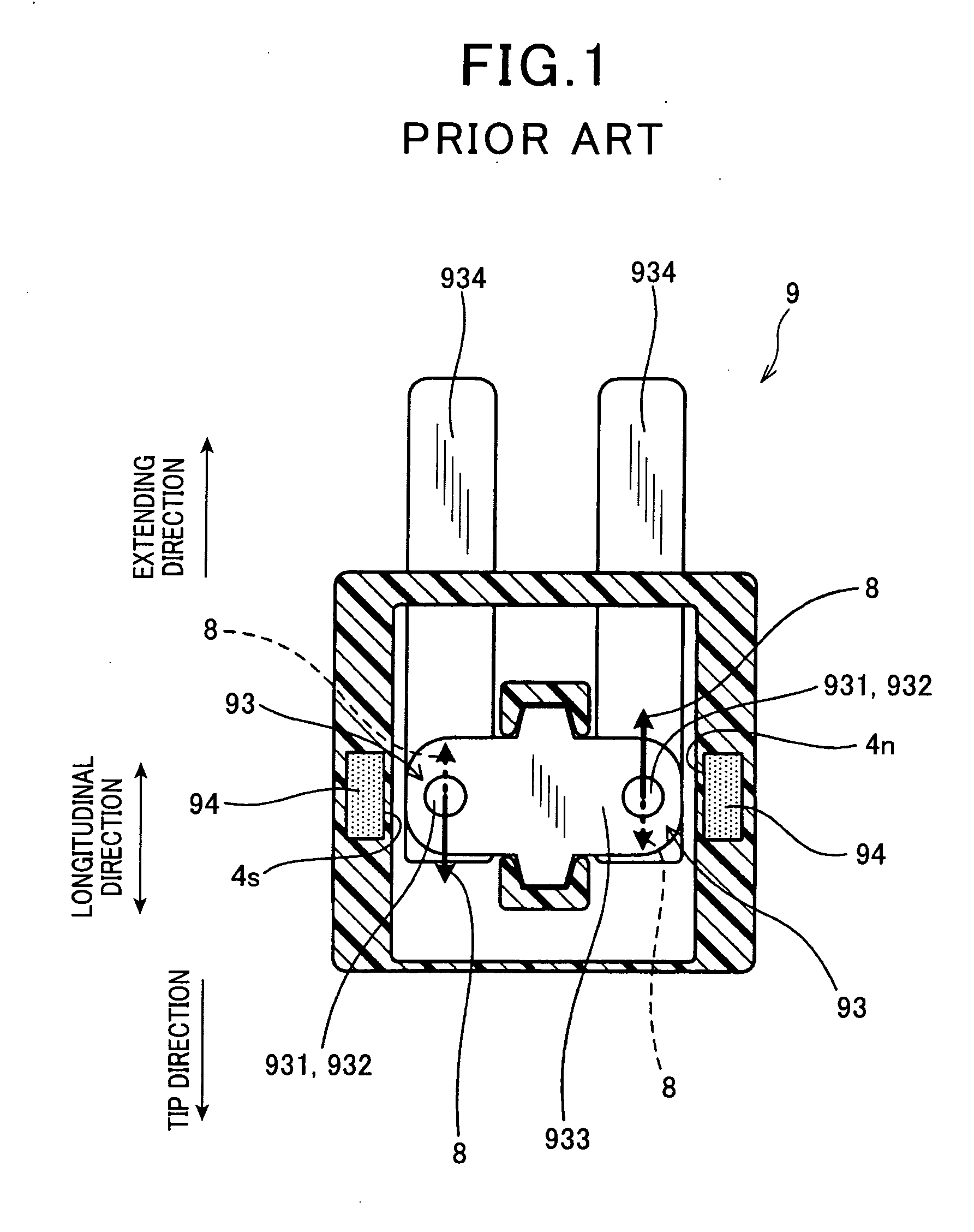
Figure 2 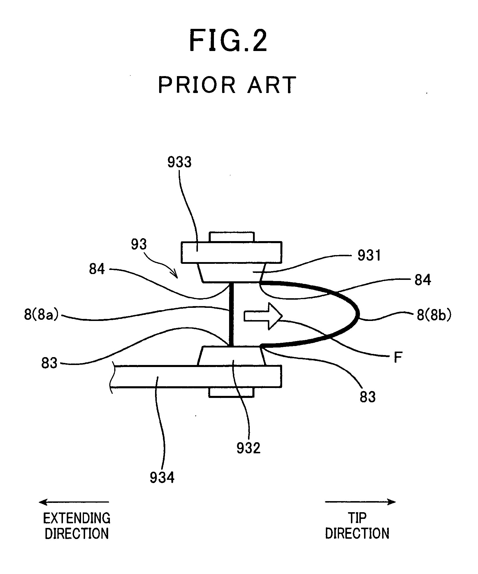
Figure 3
Abstract
Description
CROSS-REFERENCE TO RELATED APPLICATION
[0001] This application is based on and claims the benefit of priority from earlier Japanese Patent Application No. 2009-117348 filed May 14, 2009, the description of which is incorporated herein by reference.BACKGROUND OF THE INVENTION
[0002] 1. Field of the Invention
[0003] The present invention relates to an electromagnetic relay that switches between conducting and interrupting currents flowing through the electromagnetic relay, the currents being two types of currents of which magnitudes are different from each other and which flow through mutually opposite paths which are via the electromagnetic relay.
[0004] 2. Description of the Related Art
[0005] Conventionally, an electromagnetic relay is known that is used as a relay in a driving circuit in an electric vehicle, a hybrid vehicle, and the like. The electromagnetic relay is used to switch between conducting and interrupting a current.
[0006] As shown in FIG. 1 and FIG. 2, an electromagnetic relay 9...
Examples
first embodiment
[0039]With reference to FIG. 4 to FIG. 10, an electromagnetic relay according to a first embodiment of the present invention will now be described.
[0040]An electromagnetic relay 1 according to the first embodiment switches between conducting and interrupting currents in both directions having mutually different sizes.
[0041]As shown in FIG. 4 to FIG. 6, the electromagnetic relay 1 includes a coil 2, a pair of contact sections 3, arc-extinguishing magnet members 4, and a main body 10 holding various components of the electromagnetic relay 1. The coil 2 generates a magnetic force by being energized. The pair of contact sections 9 are opened and closed by the magnetic force. An arc-extinguishing magnet member 4 is disposed adjacent to the outer side of each of the contact sections 3. The arc-extinguishing magnet member 4 extends move or pull) an arc 8 generated in the contact section 3 (FIG. 8 and FIG. 9) and extinguishes the arc 8.
[0042]The pair of contact sections 3 are configured by ...
second embodiment
[0093]With reference to FIG. 11, an electromagnetic relay according to a second embodiment of the present invention will now be described.
[0094]In the present embodiment and subsequent embodiments, the components similar or identical to those employed in the foregoing first embodiment will be given the same reference numerals as those in the first embodiment for the sake of a simplified explanation.
[0095]As shown in FIG. 11, according to the second embodiment, an example is given in which the fixed holder 32 has an extension section 323 extending further to the tip side than the tip section 321. The extension section 323 is embedded within an insulating resin member 101.
[0096]In other words, a portion of the tip side of the fixed holder 32 according to the second embodiment is covered by the insulating resin member 101. The portion of the fixed holder 32 covered by the insulating resin member 101 is the extension section 323. The portion of the exposed portion positioned closest to ...
third embodiment
[0102]With reference to FIG. 12, an electromagnetic relay according to a second embodiment of the present invention will now be described.
[0103]As shown in FIG. 12, according to the third embodiment, an example is given in which the fixed holder 32 has a bent extension section 324 that bends from the tip section 321 to the side opposite of the movable holder 31. The bent extension section 324 is embedded within the insulating resin member 101.
[0104]A surface 102 of the insulating resin member 101 recedes further back than an opposing surface 325 of the fixed holder 32 opposing the movable holder 31. According to the third embodiment, the bent extension section 324 is bent further to the tip side within the insulating resin member 101.
[0105]Other configurations are the same as those according to the first embodiment.
[0106]According to the third embodiment, the fixed holder 32 can be stably fixed to the main body 10. In addition, the insulating resin member 101 is prevented from inhib...