
Pattern forming apparatus and pattern forming method
Patent Information
- Authority / Receiving Office
- US · United States
- Current Assignee / Owner
- Publication Date
- 2014-07-31
- Estimated Expiration
- Not applicable · inactive patent
Smart Images
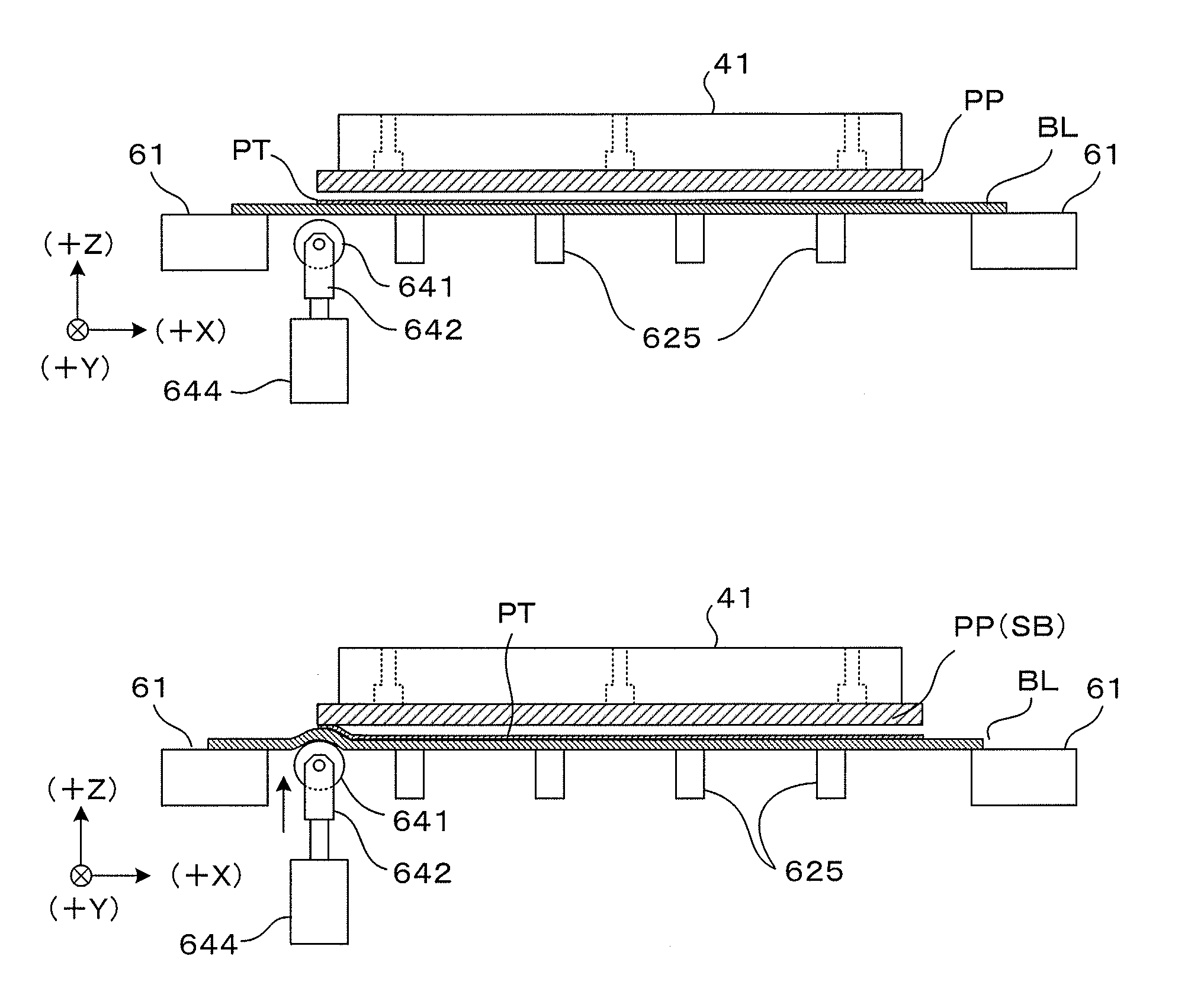
Figure 1 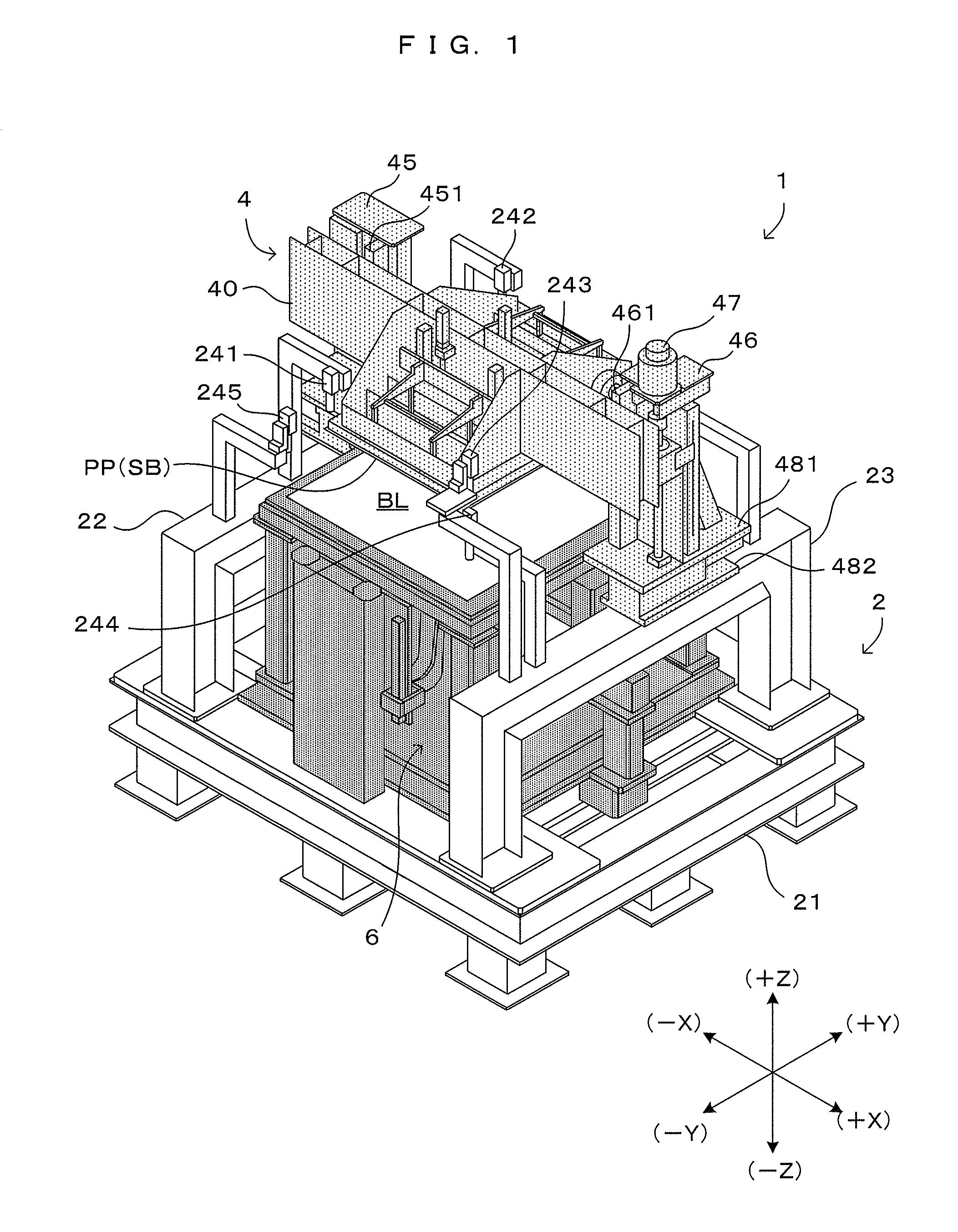
Figure 2 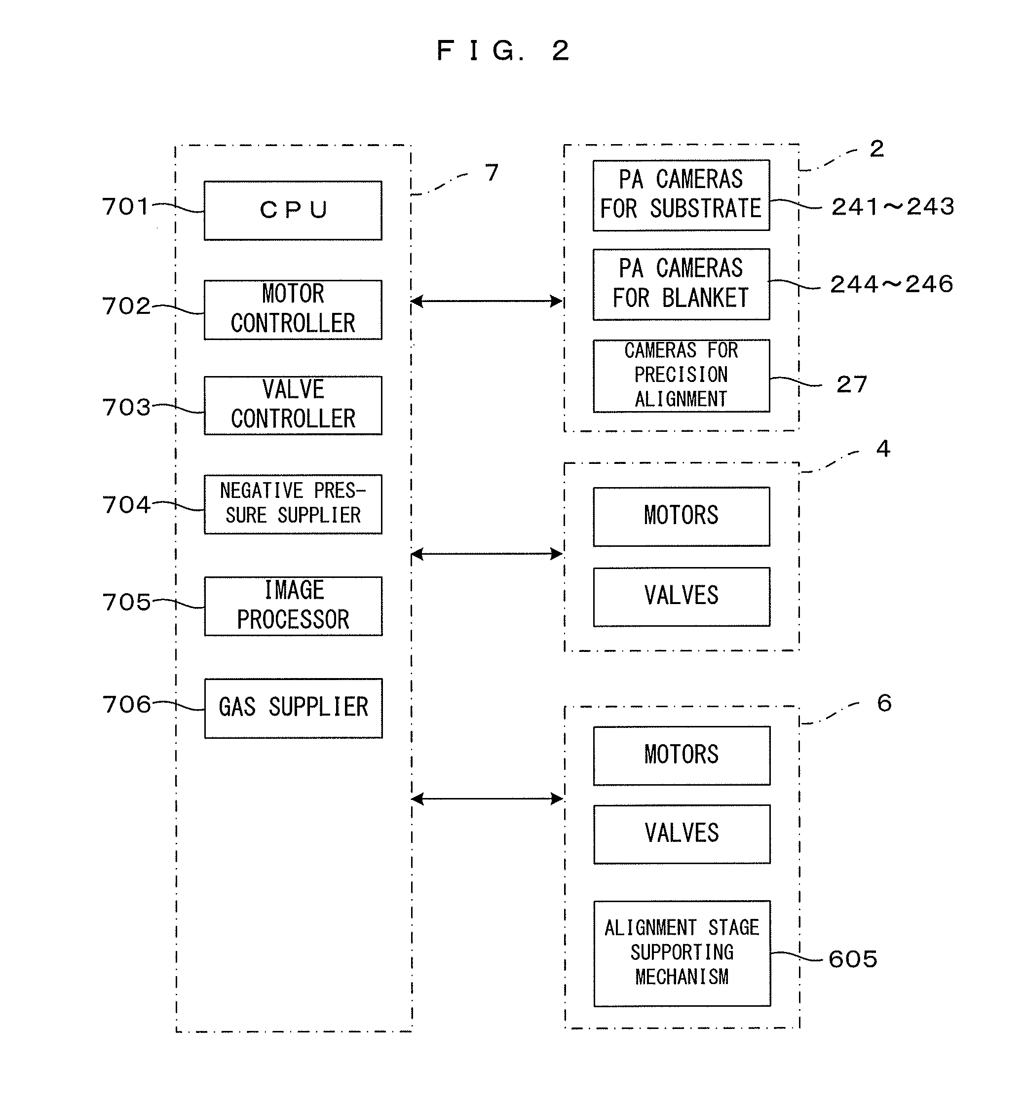
Figure 3
Abstract
Description
CROSS REFERENCE TO RELATED APPLICATION
[0001] The disclosure of Japanese Patent Applications enumerated below including specifications, drawings and claims is incorporated herein by reference in its entirety:
[0002] No. 2013-016034 filed on Jan. 30, 2013; and
[0003] No. 2013-262351 filed on Dec. 19, 2013.BACKGROUND OF THE INVENTION
[0004] 1. Field of the Invention
[0005] This invention relates to a pattern forming apparatus and a pattern forming method for patterning a pattern forming material carried on a blanket by a plate or for forming a pattern by transferring a formed pattern to a substrate.
[0006] 2. Description of the Related Art
[0007] A technique for bringing a blanket carrying a pattern into close contact with a substrate and transferring the pattern to the substrate is known as a technique for forming a pattern on a substrate such as a glass substrate or a semiconductor substrate. Further, a technique for pattern formation (patterning) by pressing a plate (negative plate) against a un...
Examples
first embodiment
[0044]FIG. 1 is a perspective view which shows a first embodiment of a pattern forming apparatus according to this invention. FIG. 2 is a block diagram which shows a control system of this pattern forming apparatus. Note that a state where an external cover is removed to show the internal configuration of the apparatus is shown in FIG. 1. XYZ orthogonal coordinate axes are set as shown on a right lower side of FIG. 1 to show directions in each figure in a unified manner. Here, an XY plane represents a horizontal plane and a Z axis represents a vertical axis. More specifically, a (+Z) direction represents a vertically upward direction. A forward direction when viewed from the apparatus is a (−Y) direction and an access to the apparatus from the outside including loading and unloading of articles is made in a Y axis direction.
[0045]This pattern forming apparatus 1 is so structured that an upper stage block 4 and a lower stage block 6 are mounted on a main frame 2. In FIG. 1, to clarif...
second embodiment
[0137]Next, a second embodiment of the pattern forming apparatus according to this invention is described. In the pattern forming apparatus of the second embodiment, the structure of a lower stage block partly differs from that of the pattern forming apparatus 1 of the first embodiment described above. On the other hand, other components in the first embodiment, i.e. the main frame 2, the upper stage block 4, the control unit 7 and the like can be basically applied as a main frame, an upper stage block, a control unit and the like in the second embodiment as they are. Accordingly, the following description is centered on points of difference from the first embodiment, particularly the structure and operation of the lower stage block. Further, the same components as in the first embodiment are denoted by the same reference signs and not described.
[0138]FIG. 17 is a view which shows a main part of the second embodiment of the pattern forming apparatus according to this invention. More...
third embodiment
[0170]Next, a third embodiment of the pattern forming apparatus according to this invention is described. In the pattern forming apparatus of the third embodiment, the structure of a lower stage block partly differs from that of the pattern forming apparatus 1 of the first embodiment described above. On the other hand, other components in the first embodiment, i.e. the main frame 2, the upper stage block 4, the control unit 7 and the like can be basically applied as a main frame, an upper stage block, a control unit and the like in the third embodiment as they are. Accordingly, the following description is centered on points of difference from the first embodiment, particularly the structure and operation of the lower stage block. Further, the same components as in the first embodiment are denoted by the same reference signs and not described.
[0171]FIG. 21 is a view which shows a main part of the third embodiment of the pattern forming apparatus according to this invention. More spe...