
Timer Device and Time Measurement System
Patent Information
- Authority / Receiving Office
- US · United States
- Current Assignee / Owner
- Publication Date
- 2015-12-31
- Estimated Expiration
- Not applicable · inactive patent
Smart Images
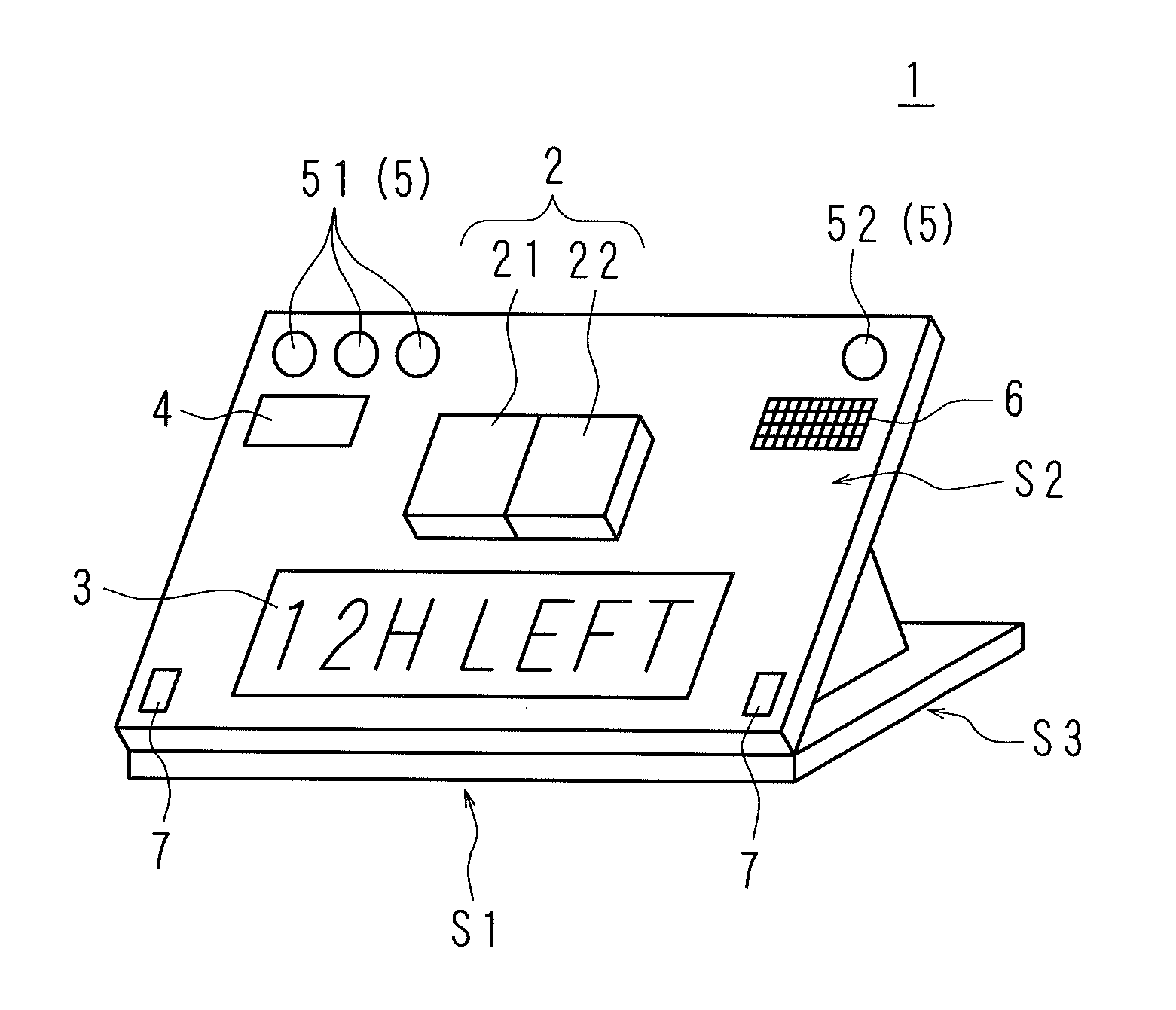
Figure 1 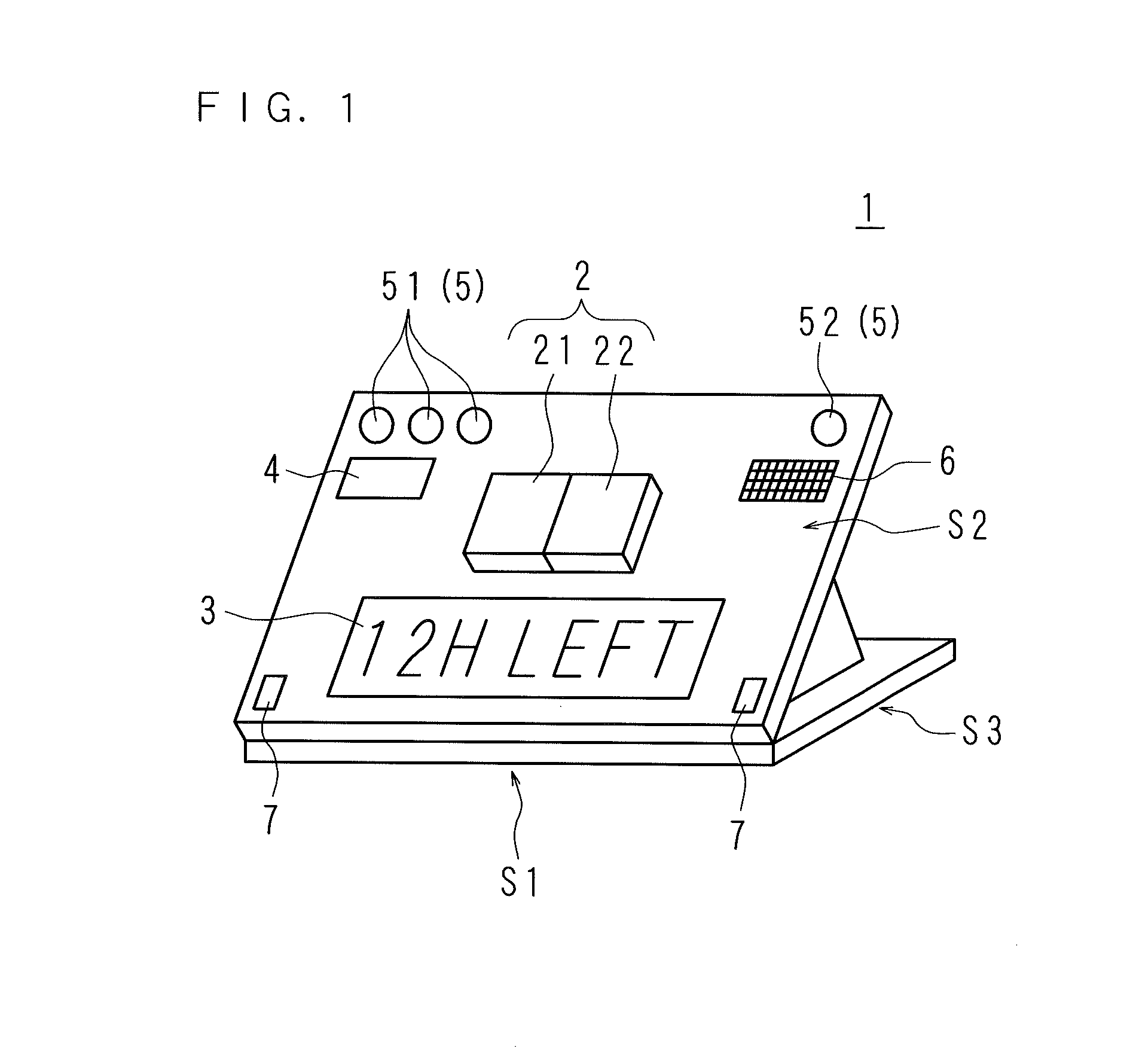
Figure 2 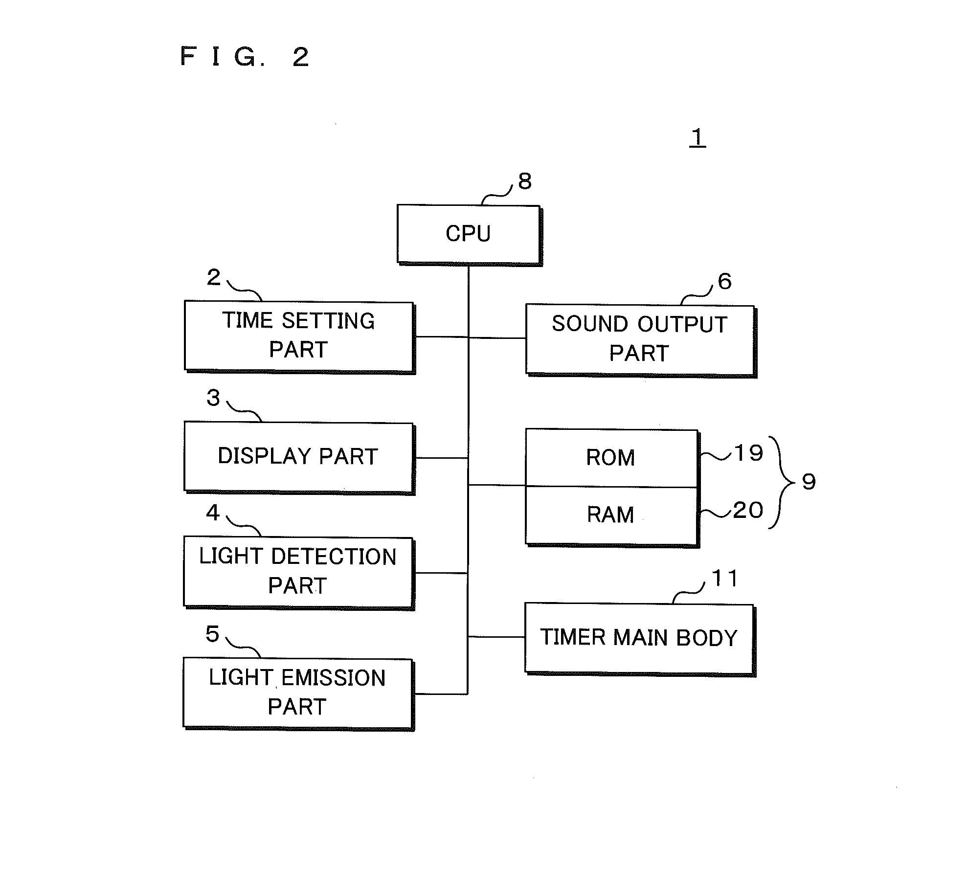
Figure 3
Abstract
Description
[0001] This application is the national phase under 35 U.S.C. §371 of PCT International Application No. PCT / JP2014 / 064324 which has an International filing date of May 29, 2014 and designated the United States of America.TECHNICAL FIELD
[0002] The present invention relates to a timer device measuring time and to a time measurement system including the timer device.DESCRIPTION OF RELATED ART
[0003] Conventionally, food items stored in a refrigerator may sometimes be expired because the user of the refrigerator cannot grasp the expiration time limits, i.e. use-before dates, for all food items that have different expiration time limits. Furthermore, as a refrigerator is restocked with food items purchased by the user one after another, a food item stored at the back of the refrigerator is hidden by another food item when the user overly puts food items into the refrigerator to exceed the capacity thereof, which causes the user to forget the existence and expiration time limit of a hidden fo...
Examples
embodiment 1
[0040]FIG. 1 is a perspective view illustrating an outer appearance of a timer device according to an embodiment of the present invention. In the present embodiment, the timer device 1 includes a time setting part 2, a display part 3, a light detection part 4, a light emission part 5, a sound output part 6 and a charging electrode 7. The timer device 1 has the shape of a clip which can nip an object, e.g., a food item, with an end of the timer device 1 as indicated by a reference code S1 in FIG. 1. Furthermore, though the appearance of the timer device 1 is formed by combining rectangular planes as indicated by reference codes S2 and S3 in the present embodiment, the appearance of the timer device 1 may also be formed by combining arbitrary planes having, for example, a circular or trianglar shape.
[0041]FIG. 2 illustrates an internal configuration of a timer device according to an embodiment of the present invention. In the present embodiment, the timer device 1 includes a time sett...
embodiment 2
[0063]Since the timer device in Embodiment 2 has the same outer appearance as that in Embodiment 1, the description thereof is not repeated here. Differences between the internal structure of the timer device in Embodiment 1 and that in Embodiment 2 will be described below. FIG. 6 illustrates an internal configuration of a timer device according to an embodiment of the present invention. In the present embodiment, a timer device 1 includes a time setting part 2, a display part 3, a light detection part 4, a light emission part 5, a sound output part 6, a CPU 8, a storage part 9, a light detection determination part 10 and a timer main body 11. The CPU 8 is connected to the time setting part 2, display part 3, light detection part 4, light emission part 5, sound output part 6, storage part 9, light detection determination part 10 and timer main body 11 through a bus or signal line. The timer main body 11 measures time related to an object. The CPU 8 generates information related to t...
embodiment 3
[0068]FIG. 7 illustrates a time measurement system including a plurality of timer devices according to the one embodiment of the present invention. A time measurement system 24 according to Embodiment 3 is used to manage, for example, nursing care schedule for ten persons. The time measurement system 24 includes a plurality of timer devices 1, a plurality of charging units 23 and a display device 25. The timer device 1 described in Embodiments 1 and 2 may be partly modified to be applied to the present embodiment as will be described later. The charging unit 23 described earlier may also be applied to the present embodiment. The display device 25 is constituted by a liquid-crystal TV or the like. In the time measurement system 24, the plurality of timer devices 1, the plurality of charging units 23 and display device 25 are connected with one another via wires or without wires.
[0069]As illustrated in FIG. 7, ten timer devices 1 are attached to one charging unit 23, and two stages of...