
Active antenna system and methods of testing
a technology of active antennas and antennas, applied in the direction of antennas, receiver monitoring, antenna details, etc., can solve the problems of high degree of measurement uncertainty, inability to represent performance, and compromise the future functionality of aas
Patent Information
- Authority / Receiving Office
- US · United States
- Patent Type
- Applications(United States)
- Current Assignee / Owner
- Publication Date
- 2016-09-01
Smart Images
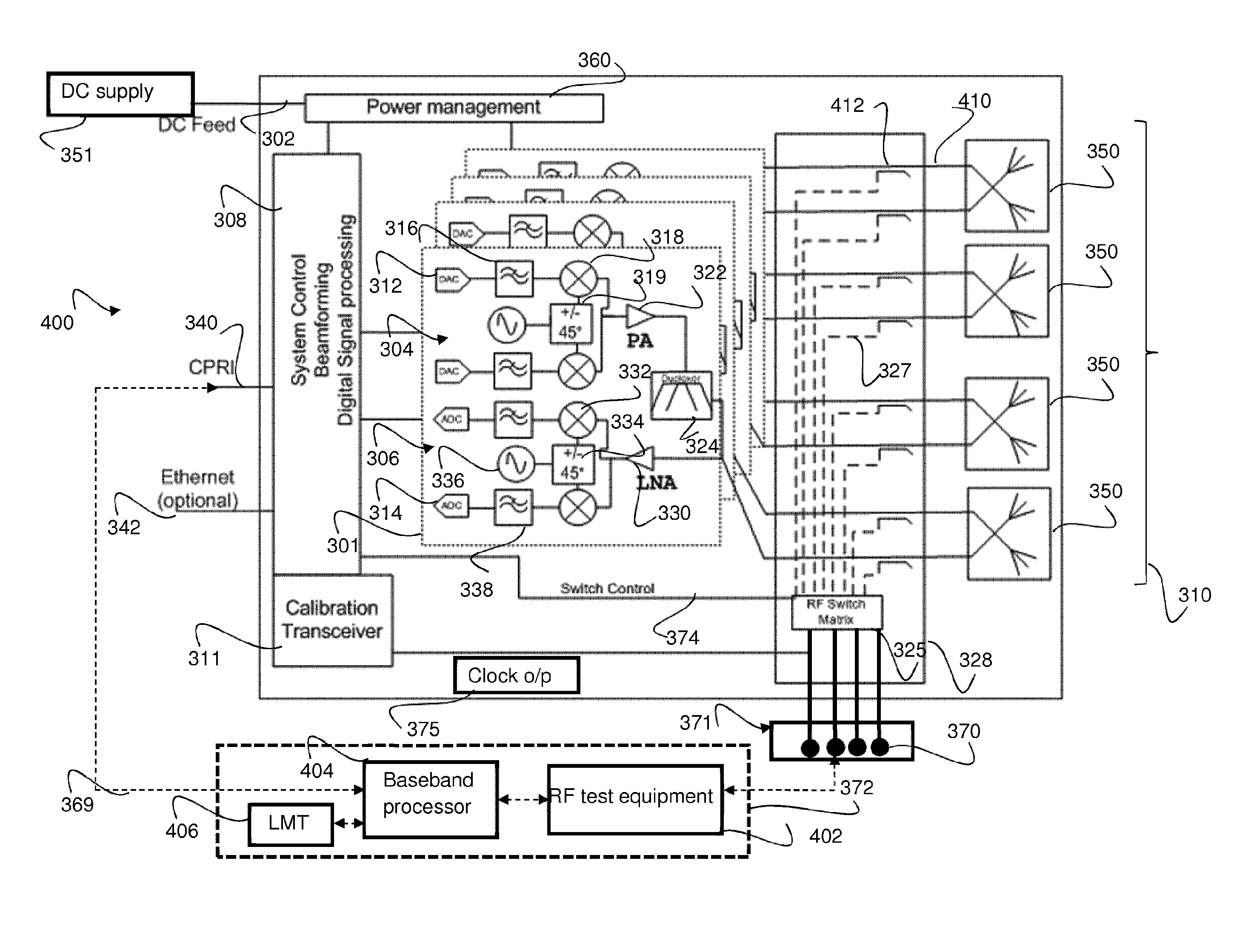
Figure 1 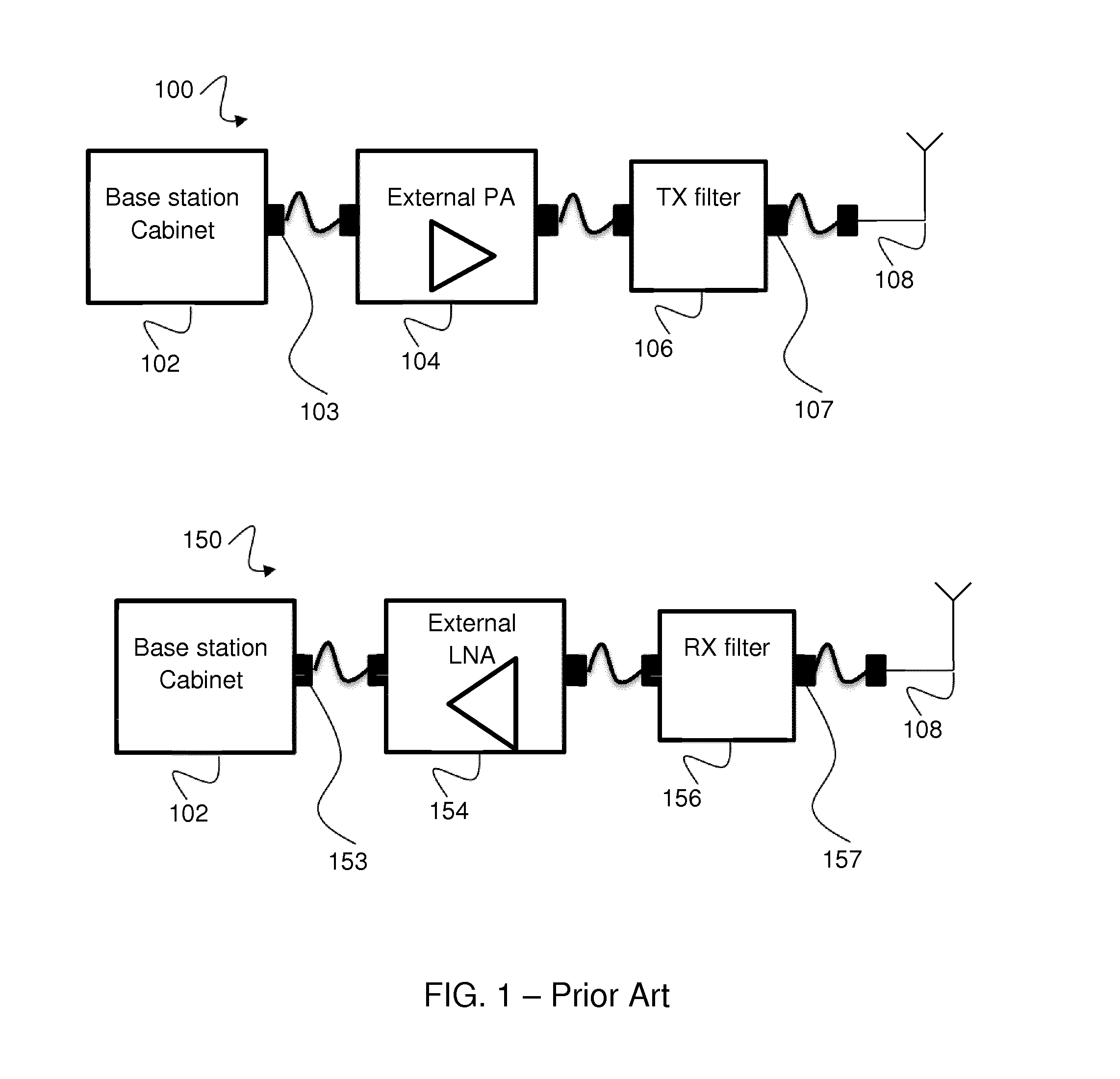
Figure 2 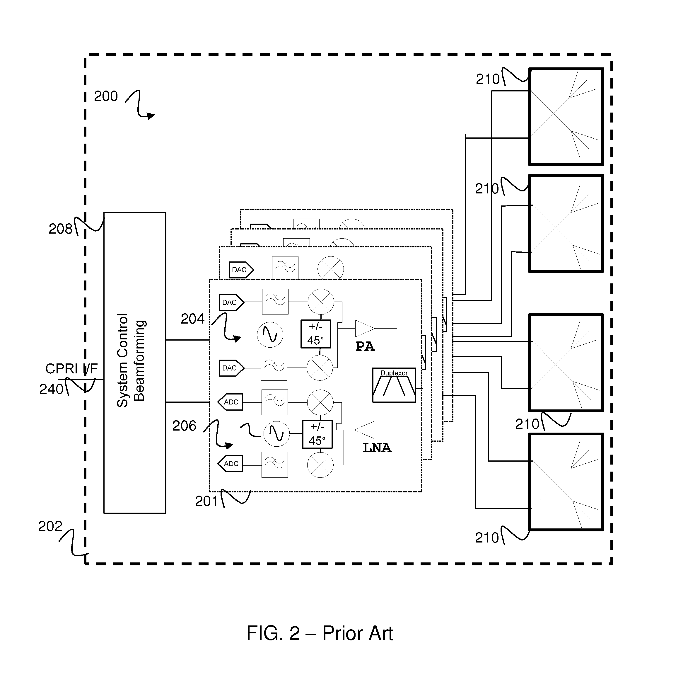
Figure 3
Abstract
Description
FIELD OF THE INVENTION
[0001] The field of the invention relates to an antenna arrangement and methods of testing, and in particular methods of testing applicable to Active Antenna Systems.BACKGROUND OF THE INVENTION
[0002] In traditional radio networks comprising of basestation(s) and passive antenna systems, there is at least one connectorised 50Ω port on the antenna and at least one connectorised 50Ω port on the basestation that allows signals to be passed there between via at least one 50Ω connectorised cable. The connectors on the base station could be, for example, 7 / 16 DIN RF connectors or N-type RF connectors. The connectorised 50Ω base station and antenna port(s) can also be used as one or more test port(s), to facilitate test and power calibration of radio frequency (RF) transceiver circuit(s) of the basestation. Advantageously, connectorised 50Ω port(s) used to allow interconnect to antenna can instead be coupled to test equipment to allow measurements to be performed on the ...
Examples
Embodiment Construction
[0049]Example embodiments of the invention are described with reference to smart (or active) antenna technology used in a wireless communication system.
[0050]The following description focuses on embodiments of the invention that are applicable to active antenna arrays employed in Universal Mobile Telecommunication System (UMTS) cellular communication systems and in particular to a UMTS Terrestrial Radio Access Network (UTRAN) operating in a 3rd generation partnership project (3GPP™) system, and evolutions to this standard such as HSPA+ or long term evolution (LTE) system. However, it will be appreciated that the invention is not limited to this particular cellular communication system, but may be applied to any wireless communication system, including satellite communication systems, employing antenna arrangements.
[0051]Referring to FIG. 3, an example of an AAS 300 adapted to support example embodiments of the invention is illustrated. The example AAS 300 comprises a CPRI interface ...