
Internal combustion engine
Patent Information
- Authority / Receiving Office
- US · United States
- Current Assignee / Owner
- Publication Date
- 2017-03-02
Smart Images
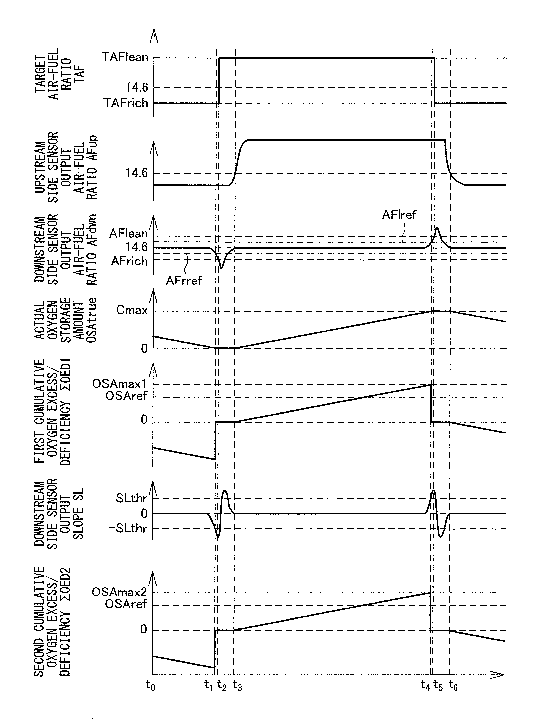
Figure 1 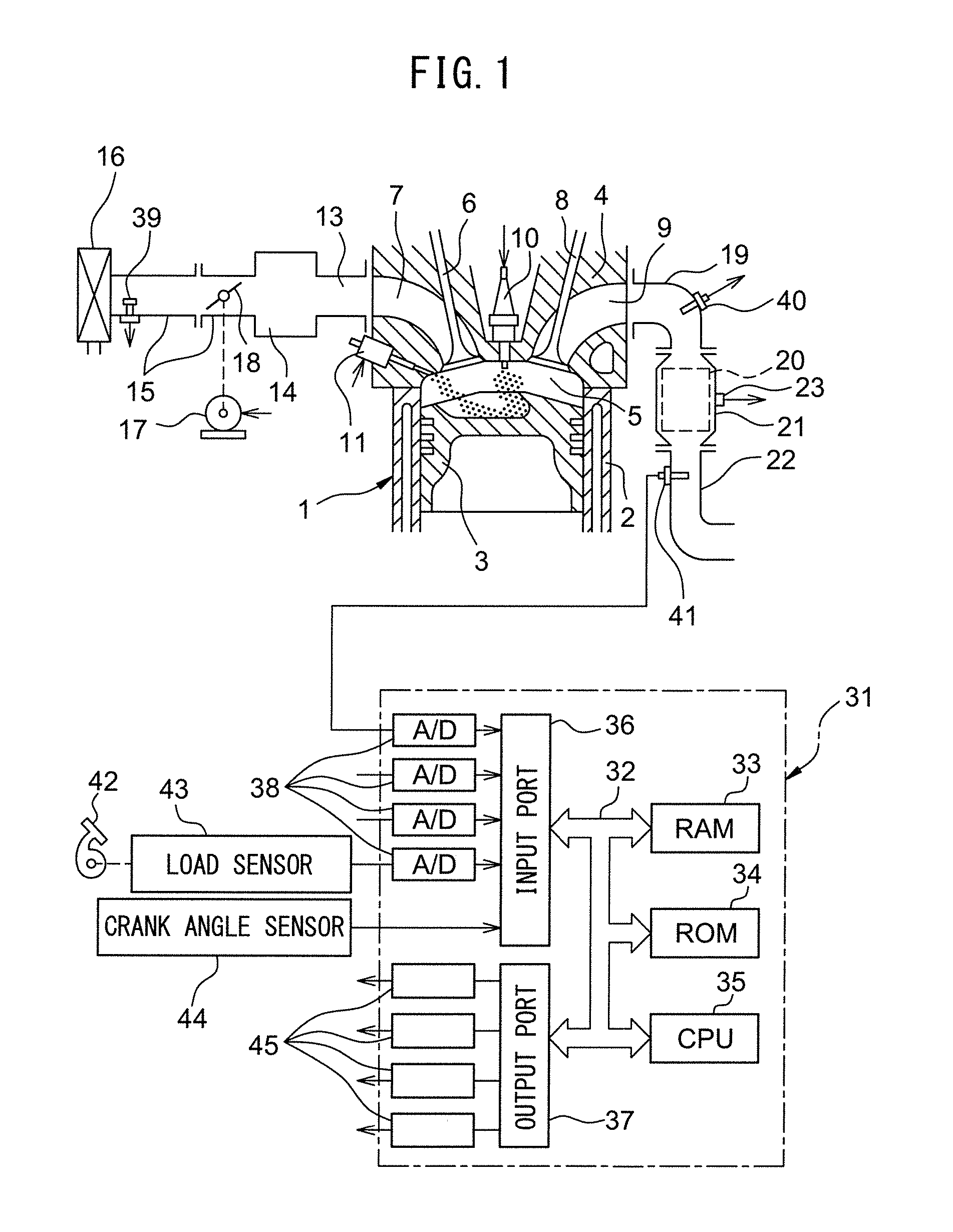
Figure 2 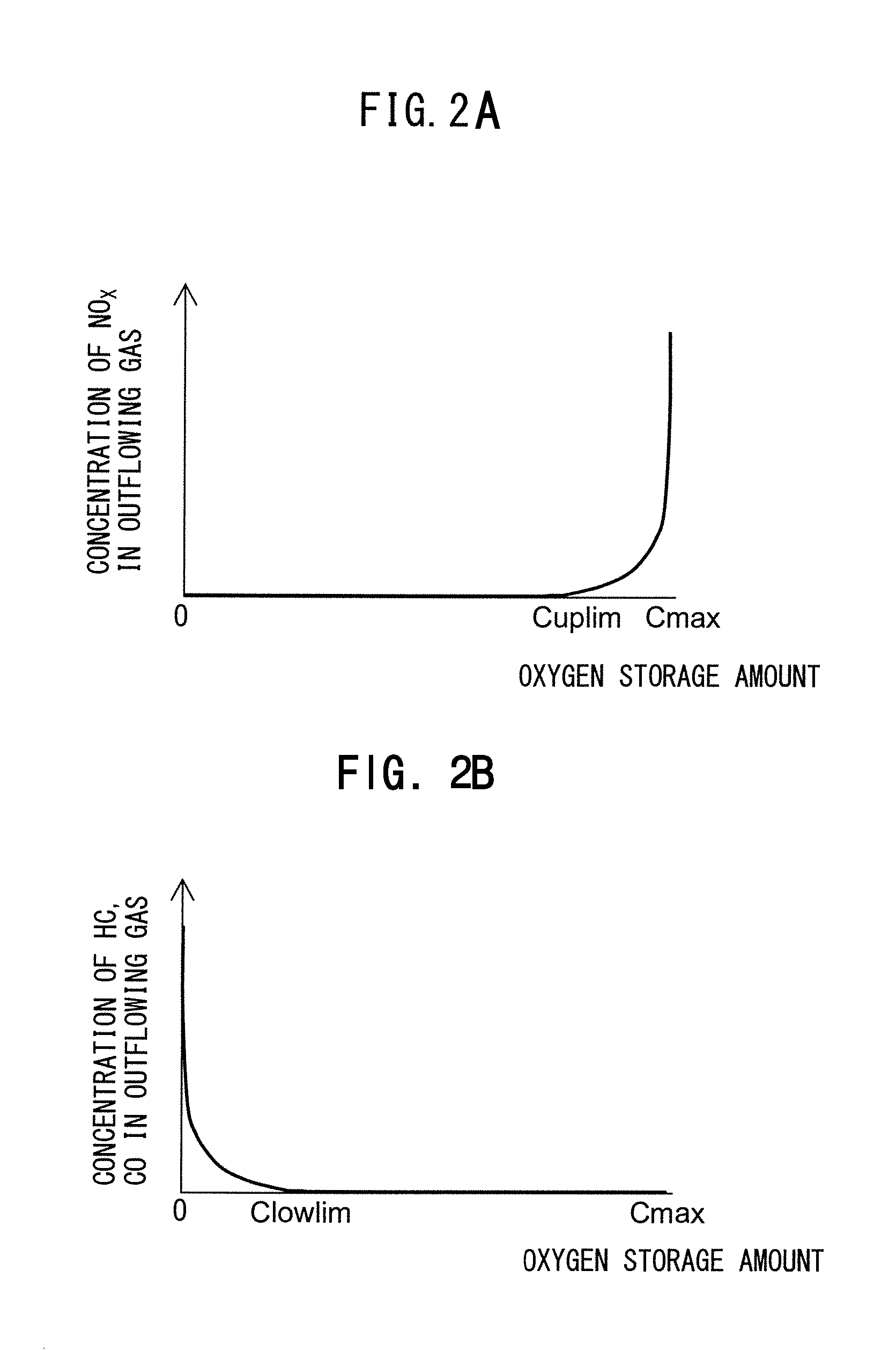
Figure 3
Abstract
Description
CROSS-REFERENCE TO RELATED APPLICATIONS
[0001] This application claims priority to Japanese Patent Application No. 2015-170917 filed on Aug. 31, 2015, the entire contents of which is hereby incorporated by reference.TECHNICAL FIELD
[0002] The present disclosure relates to an internal combustion engine.BACKGROUND ART
[0003] In the past, in an internal combustion engine, it was known to provide an exhaust passage with an exhaust purification catalyst able to remove harmful substances in exhaust gas. However, the exhaust purification catalyst sometimes deteriorates along with time due to poisoning, heat degradation, etc. If the exhaust purification catalyst deteriorates, the exhaust purification catalyst falls in purification efficiency. For this reason, it is desirable to be able to quickly detect if the exhaust purification catalyst has deteriorated and the exhaust purification catalyst is abnormal. Therefore, in the internal combustion engine described in PLT 1, a downstream side sensor d...
Examples
first embodiment
[0042]First, referring to FIG. 1 to FIG. 12, a first embodiment of the present disclosure will be explained.
[0043]
[0044]FIG. 1 is a view which schematically shows an internal combustion engine in the first embodiment of the present disclosure. The internal combustion engine in the present embodiment is, for example, carried in a vehicle. Referring to FIG. 1, 1 indicates an engine body, 2 a cylinder block, 3 a piston which reciprocates inside the cylinder block 2, 4 a cylinder head which is fastened to the cylinder block 2, 5 a combustion chamber which is formed between the piston 3 and the cylinder head 4, 6 an intake valve, 7 an intake port, 8 an exhaust valve, and 9 an exhaust port. The intake valve 6 opens and closes the intake port 7, while the exhaust valve 8 opens and closes the exhaust port 9.
[0045]As shown in FIG. 1, at the center part of the inside wall surface of the cylinder head 4, a spark plug 10 is arranged. A fuel injector 11 is arranged around the inside wall surface...
second embodiment
[0143]Next, a second embodiment of the present disclosure will be explained. Note that, the configuration and control of the internal combustion engine of the second embodiment are basically similar to the internal combustion engine of the first embodiment, so, in the following description, parts different from the first embodiment will primarily be explained.
[0144]The inventors of the present application obtained the following discoveries relating to fluctuations of output of the downstream side air-fuel ratio sensor 41 in the case where the exhaust purification catalyst 20 is normal and the temperature of the exhaust purification catalyst 20 is low. Specifically, in active control, from when switching the target air-fuel ratio from the rich set air-fuel ratio to the lean set air-fuel ratio to when the output air-fuel ratio of the downstream side air-fuel ratio sensor 41 reaches the lean judged air-fuel ratio, the output slope of the downstream side air-fuel ratio sensor 41 becomes...
third embodiment
[0165]Next, a third embodiment of the present disclosure will be explained. Note that, the configuration and control of the internal combustion engine of the third embodiment are basically similar to the internal combustion engine of the first embodiment and second embodiment, so, in the following description, parts different from the first embodiment and second embodiment will primarily be explained. In the third embodiment, in addition to the abnormality diagnosis of the exhaust purification catalyst 20, the abnormality diagnosis of the downstream side air-fuel ratio sensor 41 is performed.
[0166]In the third embodiment, to diagnose the exhaust purification catalyst 20 and downstream side air-fuel ratio sensor 41 for abnormality, active control similar to the first embodiment and second embodiment is performed. Therefore, the air-fuel ratio control unit alternately switches the target air-fuel ratio of the inflowing exhaust gas between a rich set air-fuel ratio richer than the stoi...