
Implement with telescopically movable stem for stirring or comminuting food
Patent Information
- Authority / Receiving Office
- US · United States
- Current Assignee / Owner
- Publication Date
- 2018-05-03
Smart Images
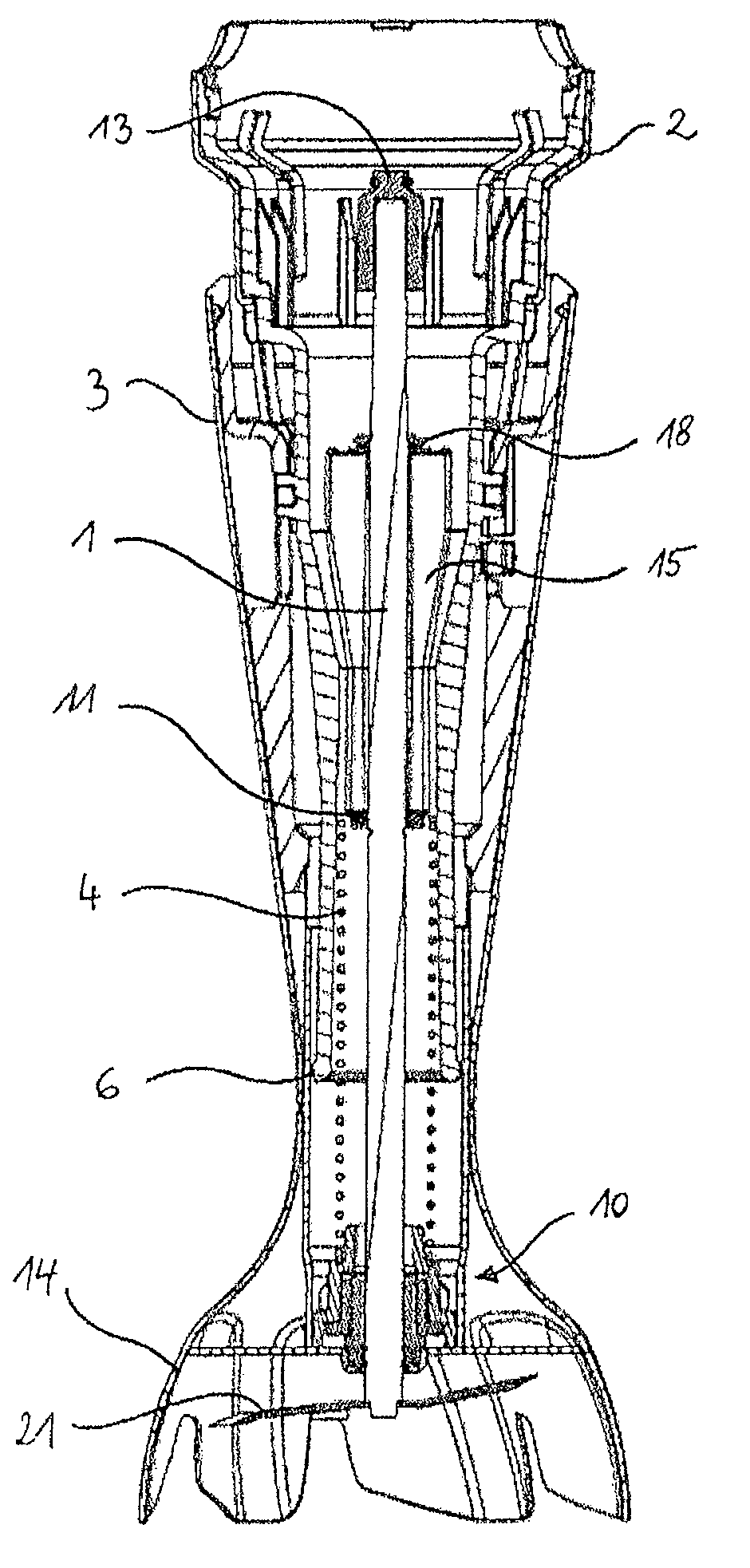
Figure 1 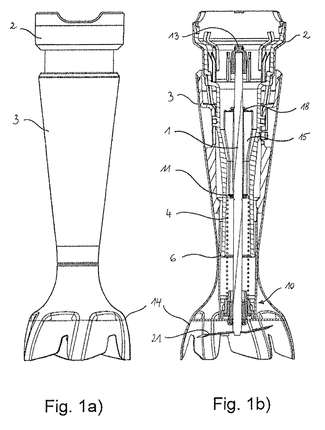
Figure 2 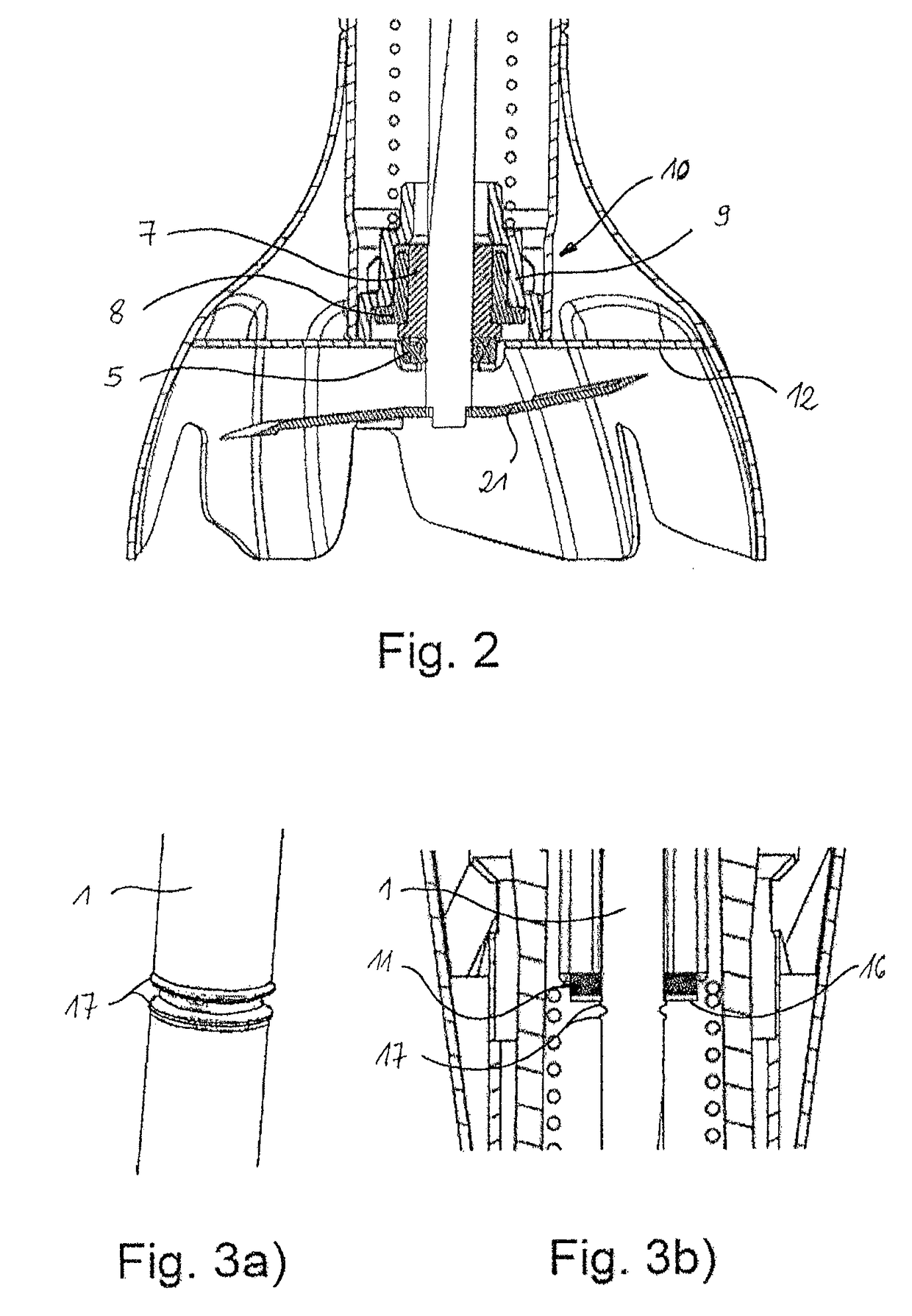
Figure 3
Abstract
Description
[0001] The present invention relates to an implement, particularly an electrically driven hand blender, with a telescopically movable stem for stirring or comminuting food in accordance with the preamble of claim 1.BACKGROUND ART
[0002] Conventional implements for stirring or comminuting food are known, for example, from WO 96 / 10944 A1 or EP 0 724 857 A1. A wide variety of such implements are being used particularly in daily food preparation, to comminute and blend foodstuffs, for example. One kind of implements that have become widespread in private households, but also in professionally run gastronomy venues, are hand blenders. Such hand blenders typically have a motor housing which adjoins an elongate housing part, the so-called stem, which in turn merges at its end into a shield having an open-bottomed end, the so-called bell. In the motor housing, a drive motor is arranged which drives a working shaft that is inserted through the stem and usually has attached at its end, in the re...
Examples
Embodiment Construction
[0040]FIG. 1a) shows a lateral view of the stem of an implement according to the invention, in this example a hand blender. The stem is divided into an inner assembly 2 and an outer assembly 3. The inner assembly 2 is capable of moving telescopically into and out of the outer assembly 3. As can be seen in the longitudinal sectional view of the stem in FIG. 1b), the shaft 1 is guided in the inner assembly 2 and is supported therein by means of an axial bearing 11. In addition, the inner assembly 2 is configured so that it can be detachably coupled with the hand blender motor housing (not shown here), which simultaneously forms the handle for the user, wherein no relative movement is allowed between motor housing and inner stem assembly 2 in the coupled state. This also connects the shaft 1 with the motor shaft via the shaft coupling 13.
[0041]At the lower end of the outer assembly 3 there is a bell-shaped shield 14 for the cutter 21 (working part) attached to the bottom end of the sha...