
Switch valve for controlling a hydraulic fluid flow and connecting rod for a variable compression internal combustion engine with a switch valve
Patent Information
- Authority / Receiving Office
- US · United States
- Current Assignee / Owner
- Publication Date
- 2019-03-07
Smart Images
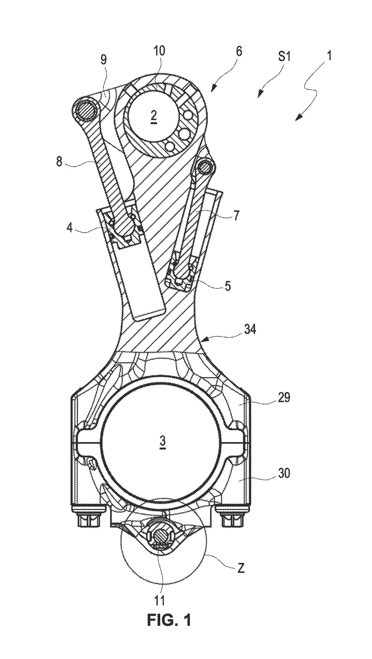
Figure 1 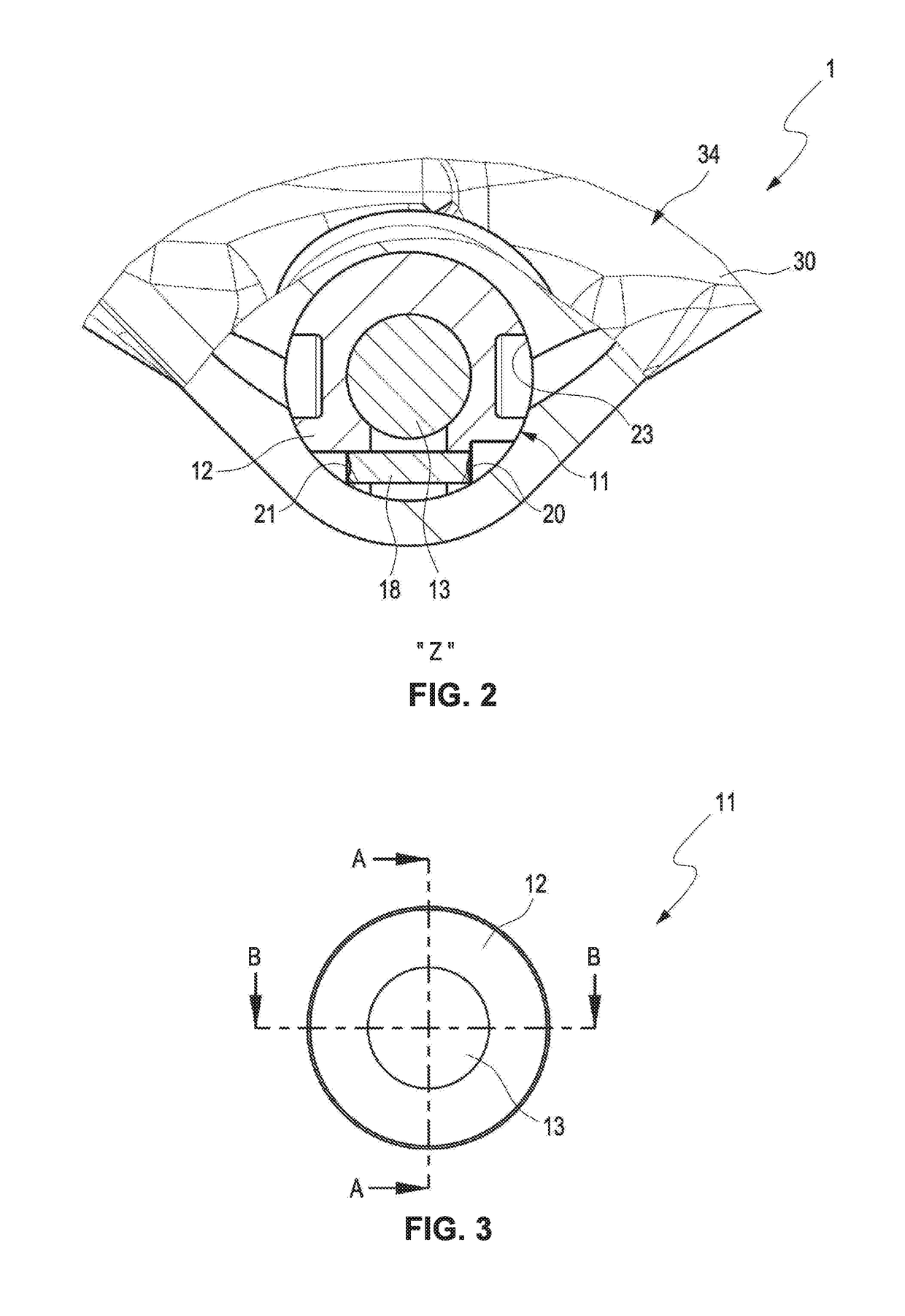
Figure 2 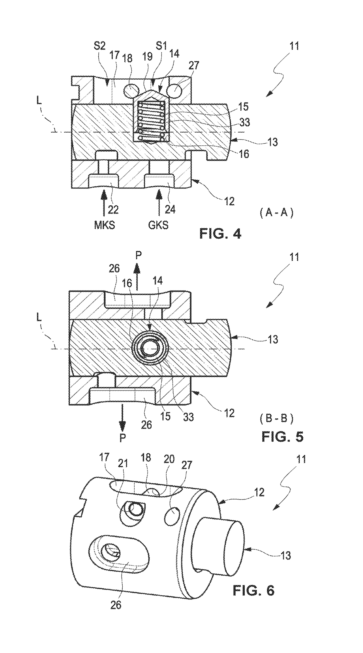
Figure 3
Abstract
Description
RELATED APPLICATIONS
[0001] This application claims priority from and incorporates by reference German patent applicationsDE 10 2017 120 255.2 filed on Sep. 4, 2017, andDE 10 2018 107 108.6 filed on Mar. 26, 2018.FIELD OF THE INVENTION
[0002] The invention relates to a switch valve for controlling a hydraulic fluid flow, in particular for a connecting rod for a variable compression internal combustion engine with an eccentrical element adjustment arrangement for adjusting an effective connecting length. Furthermore, the invention relates to a connecting rod with the switch valve.BACKGROUND OF THE INVENTION
[0003] In internal combustion engines a high compression ratio has a positive effect upon an efficiency of the internal compression engine. In internal combustion engines with external ignition, in particular gasoline engines that have a fixed compression ratio, the compression ratio, however, may only be selected high enough so that a so-called “knocking” of the internal combustion eng...
Examples
first embodiment
[0055]FIGS. 2 through 12 illustrate various views and sectional views of a switch valve 11 according to the invention, or of components of the switch valve 11 which is provided in particular for a known connecting rod 1 for a variable compression internal combustion engine that is illustrated in FIG. 1.
[0056]The connecting rod 1 illustrated in FIG. 1 includes a rod element 34, including a connecting rod body 29, a connecting rod cover 30 and an eccentrical element adjustment arrangement 6 with an eccentrical element 10 that is at least partially arranged in a connecting rod bearing eye. The eccentrical element adjustment arrangement 6 adjusts an effective connecting rod length. A connecting rod length is a distance of a center axis of a crank bearing eye 3 from a center axis of a connecting rod bearing eye 2.
[0057]A relative rotation of the adjustable eccentrical element adjustment arrangement 6 is initiated by an impact of mass and load forces of the internal combustion engine whic...
second embodiment
[0062]In order to receive the non-illustrated safety pin the connecting rod 1 includes boreholes 32 which are illustrated in the second embodiment in FIG. 14, whereas the valve housing 12 includes corresponding boreholes 27 (illustrated in FIG. 9) into which a safety pin can be impressed. The boreholes 32 of the connecting rod 1 are configured, e.g., as pass-through boreholes to simplify fabrication.
[0063]In the cross sectional view of FIG. 2 the valve housing 12 of the switch valve 11 that is impressed into the borehole 23 of the connecting rod cover is illustrated with the internally supported tapping element 13. The interlocking pin 18 is arranged in the boreholes 20, 21 transversal to the axis of the valve housing 12.
[0064]In the cross sectional view of the switch valve 11 in FIG. 4, furthermore, the two hydraulic connections 22, 24, are arranged which are respectively associated with the supply of the hydraulic chambers of the mass force side (MKS) or the gas force side (GKS) o...