
Electric motor driven pump
Patent Information
- Authority / Receiving Office
- US · United States
- Current Assignee / Owner
- Publication Date
- 2019-10-31
Smart Images
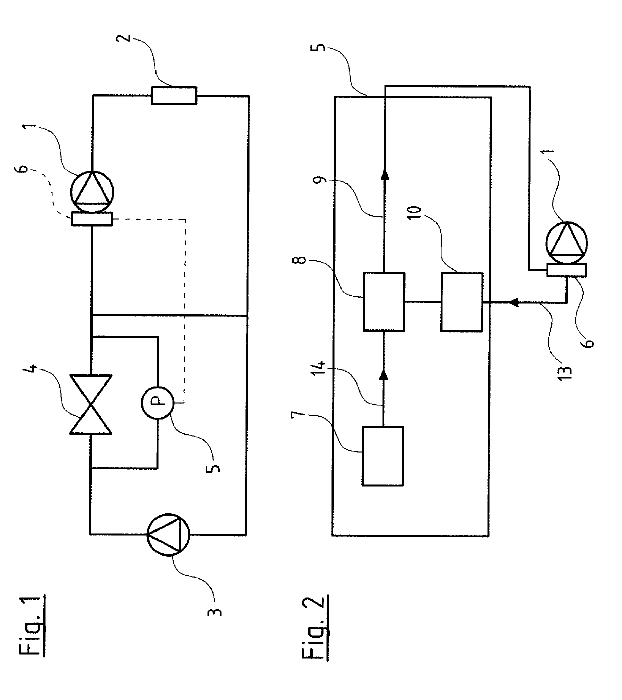
Figure 1 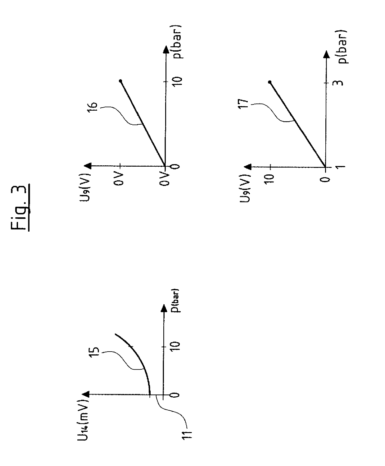
Figure 2 
Figure 3
Abstract
Description
CROSS REFERENCE TO RELATED APPLICATIONS
[0001] This application is a United States National Phase Application of International Application PCT / EP2017 / 083018 filed Dec. 15, 2017, and claims the benefit of priority under 35 U.S.C. § 119 of European Application 16205701.2, filed Dec. 21, 2016, the entire contents of which are incorporated herein by reference.TECHNICAL FIELD
[0002] The invention relates to an electromotorically driven pump with control electronics which are provided for the connection of at least one sensor.TECHNICAL BACKGROUND
[0003] Pumps of this type and which are provided with control electronics typically comprise a frequency converter which renders it possible to adapt operating points of the pump in an almost arbitrary manner within a defined power spectrum. For this, a differential pressure sensor for example is provided on the part of the pump. It is particularly with pump systems as well as pumps of a larger construction type, that it is counted as belonging to the ...
Examples
Embodiment Construction
[0034]Referring to the drawings, FIG. 1 by way of example shows a hydraulic circuit, with a first pump 1 which delivers to a consumer 2, whose exit is connected to the entry of the pump 1 as well as to the entry of a second pump 3, at the exit of which second pump a valve 4 connects, said valve connecting the exit of the second pump 3 to the entry of the first pump 1.
[0035]A pressure sensor 5 is arranged parallel to the valve 4. This pressure sensor 5 is a differential pressure sensor which detects the pressure drop at the valve 4. The sensor 5 is connected to control electronics 6 of the pump 1 which form part of frequency converter electronics of an electric motor driving the centrifugal pump 1.
[0036]The control electronics 6 are configured on the one hand to recognize the connected pressure sensor 5 as a pressure sensor and on the other hand to set the measurement range of this pressure sensor 5, as is described further below. The electrical signal of the pressure sensor 5 corres...