
Laminated image pickup device, image pickup apparatus, image pickup method, and recording medium recorded with image pickup program
Patent Information
- Authority / Receiving Office
- US · United States
- Current Assignee / Owner
- Publication Date
- 2020-12-31
- Estimated Expiration
- Not applicable · inactive patent
Smart Images
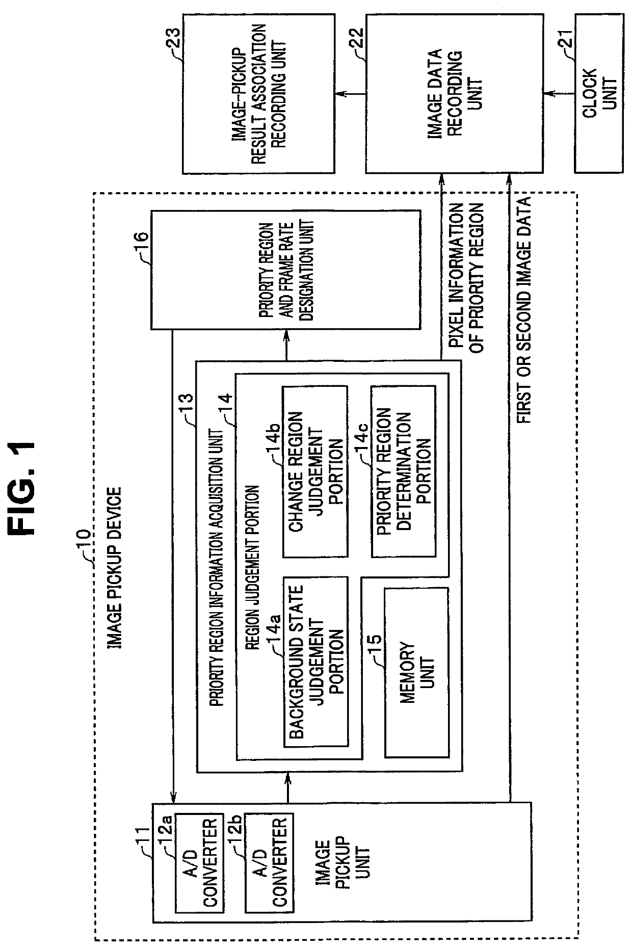
Figure 1 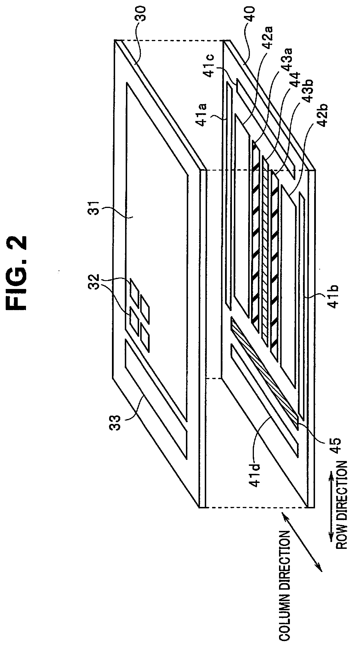
Figure 2 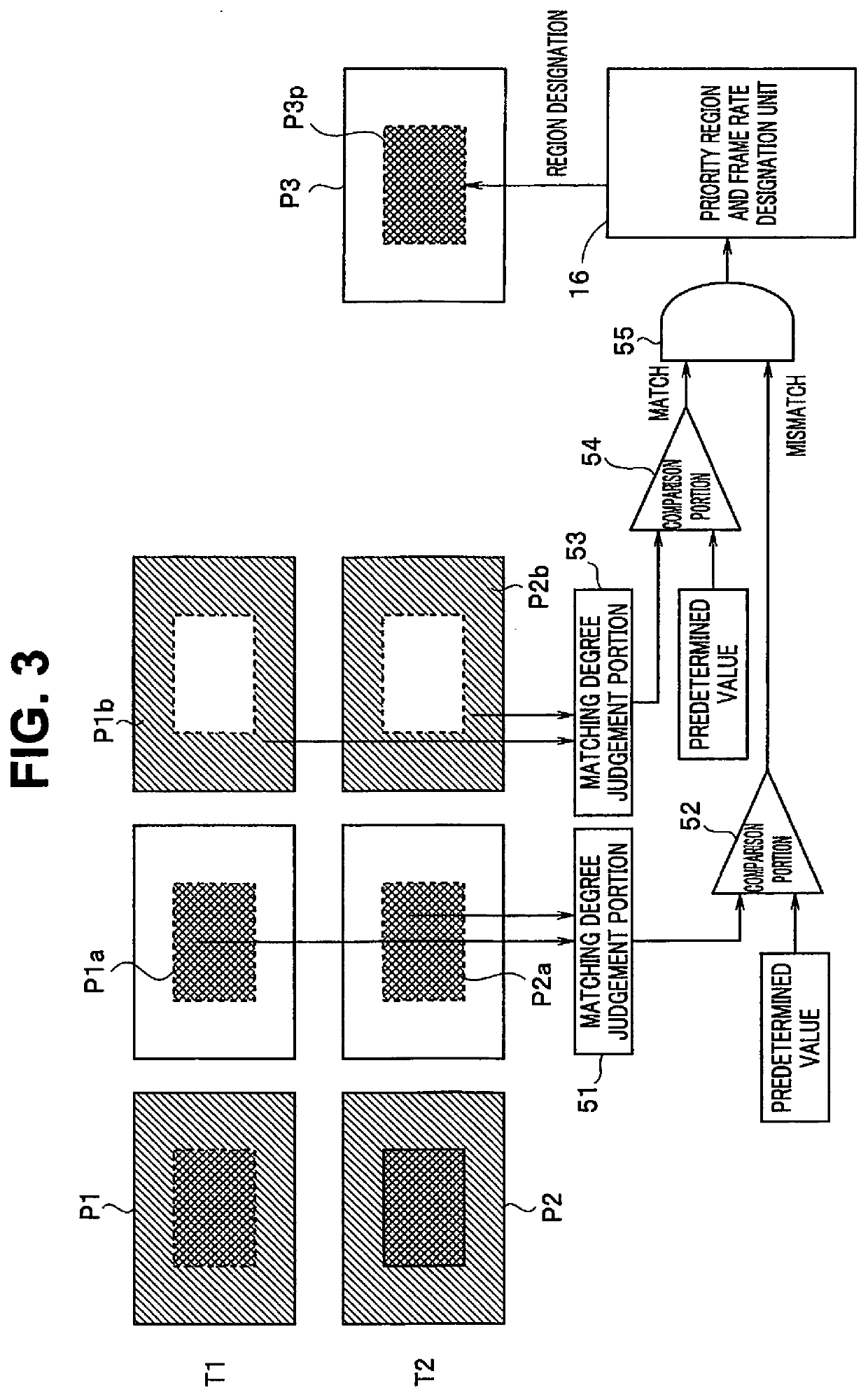
Figure 3
Abstract
Description
CROSS REFERENCE TO RELATED APPLICATION
[0001] This application claims the benefit of Japanese Application No. 2019-120158 filed in Japan on Jun. 27, 2019, the contents of which are incorporated herein by this reference.BACKGROUND OF THE INVENTION1. Field of the Invention
[0002] The present invention relates to a laminated image pickup device, an image pickup apparatus, an image pickup method, and a recording medium recorded with an image pickup program which enable high-speed reading.2. Description of the Related Art
[0003] In recent years, portable devices (photographing devices) with a photographing function such as digital cameras have become widespread. As an image pickup device used in these types of photographing devices, a laminated image pickup device has been developed. The laminated image pickup device has a laminated structure of a layer in which a pixel unit (sensor unit) having pixels for image pickup is formed (hereinafter, referred to as a sensor layer) and a layer in which...
Examples
first embodiment
[0028]FIG. 1 is a block diagram illustrating a circuit configuration of an image pickup apparatus adopting a laminated image pickup device according to a first embodiment of the present invention. In addition, FIG. 2 is a perspective view schematically illustrating an example of a configuration of the laminated image pickup device according to the first embodiment.
[0029]In the present embodiment, only some of pixel regions (hereinafter, referred to as priority regions) in all effective pixel regions configured in a sensor unit of the image pickup device is read, and thus a high reading frame rate can be achieved. In such a case, according to the present embodiment, a priority region to be read is estimated according to a predetermined rule, for example, based on an image formed by effective pixels of all effective pixel regions. The priority region limits a read region, and may be called a limited image acquisition region.
[0030]First, a configuration of a laminated image pickup devi...
second embodiment
[0087]FIG. 7 is a block diagram illustrating a circuit configuration of an image pickup apparatus according to a second embodiment of the present invention. Further, FIG. 8 is a perspective view schematically illustrating an example of a configuration of a laminated image pickup device in FIG. 7. In FIGS. 7 and 8, the same components as the components in FIGS. 1 and 2 are denoted by the same reference numerals and will not be presented.
[0088]The priority region is determined by the processing circuit unit 44 configured by the logic circuits in the first embodiment. On the other hand, the priority region is determined by an inference device in the present embodiment.
[0089]In the present embodiment, an example will be described in which a laminated image pickup device 70 having a three-layer structure is adopted. An image pickup device 70 may be configured to have a two-layer structure.
[0090]First, a configuration of an image pickup device 70 will be described with reference to FIG. 8...
third embodiment
[0129]FIG. 11 is a block diagram illustrating a circuit configuration of an image pickup apparatus according to a third embodiment of the present invention. In FIG. 11, the same components as the components in FIG. 7 are denoted by the same reference numerals and will not be presented. In the present embodiment, an example is represented in which an image pickup device 102 including the inference engine 72 illustrated in FIG. 7 is applied to an image pickup apparatus 100. In the present embodiment, an inference model 72a of the image pickup device 102 can be rewritten.
[0130]As the image pickup apparatus 100 in FIG. 11, not only a digital camera or a video camera, but also a camera built in a smartphone or a tablet terminal may be adopted. Naturally, the image pickup apparatus 100 can also be applied to a camera unit of various image inspection apparatuses used in in-vehicle or process inspection, constructions, industrial fields such as security-related, or medical fields. This is b...