
Honeycomb structure and exhaust gas purifying device
Patent Information
- Authority / Receiving Office
- US · United States
- Current Assignee / Owner
- Publication Date
- 2021-12-16
Smart Images
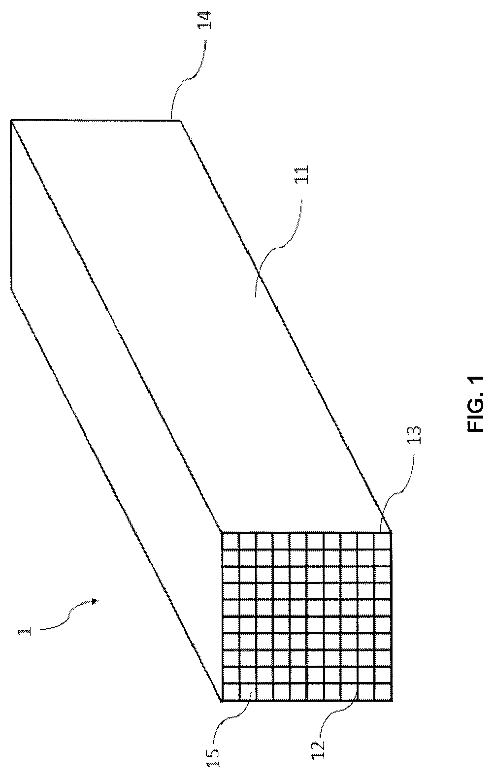
Figure 1 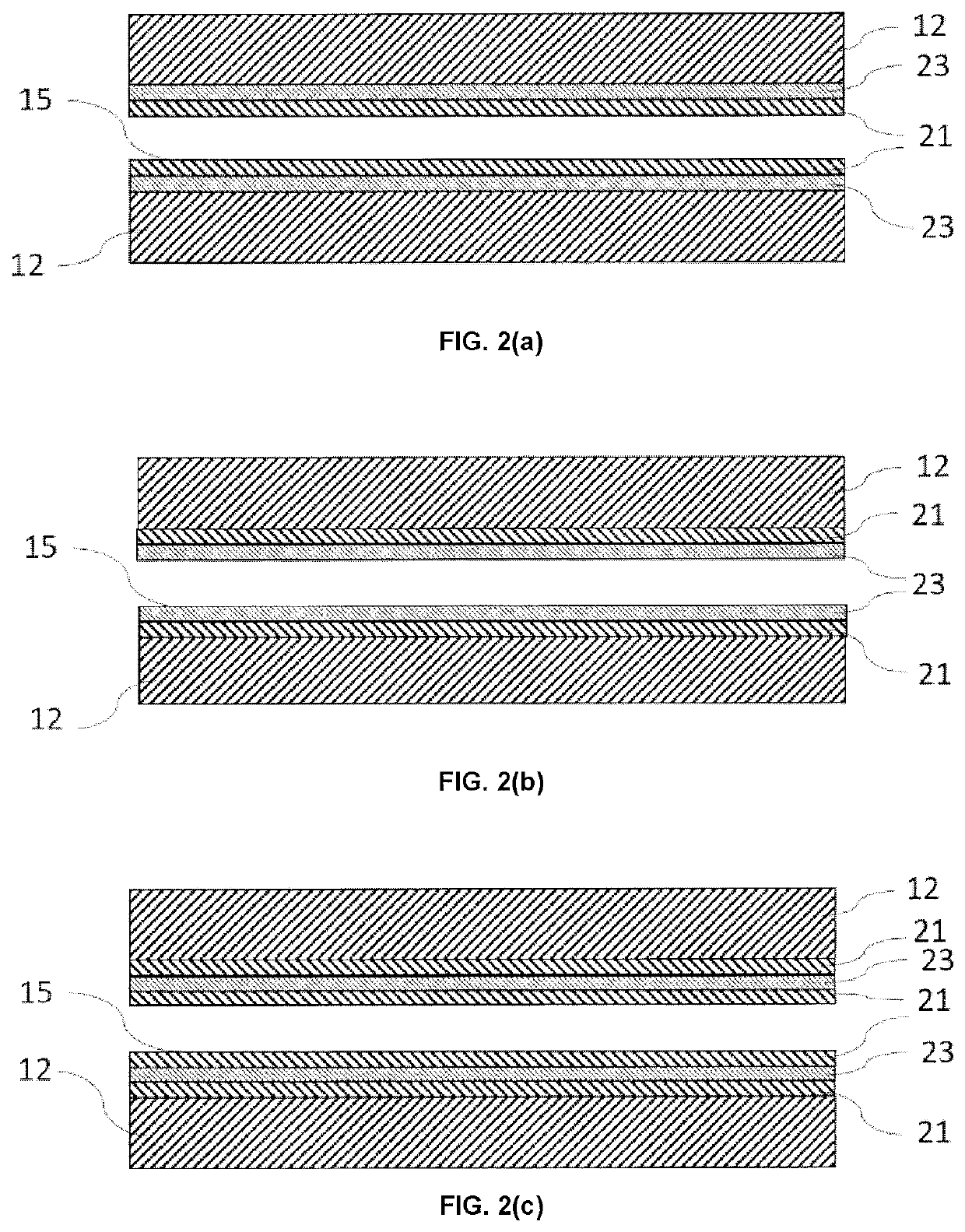
Figure 2 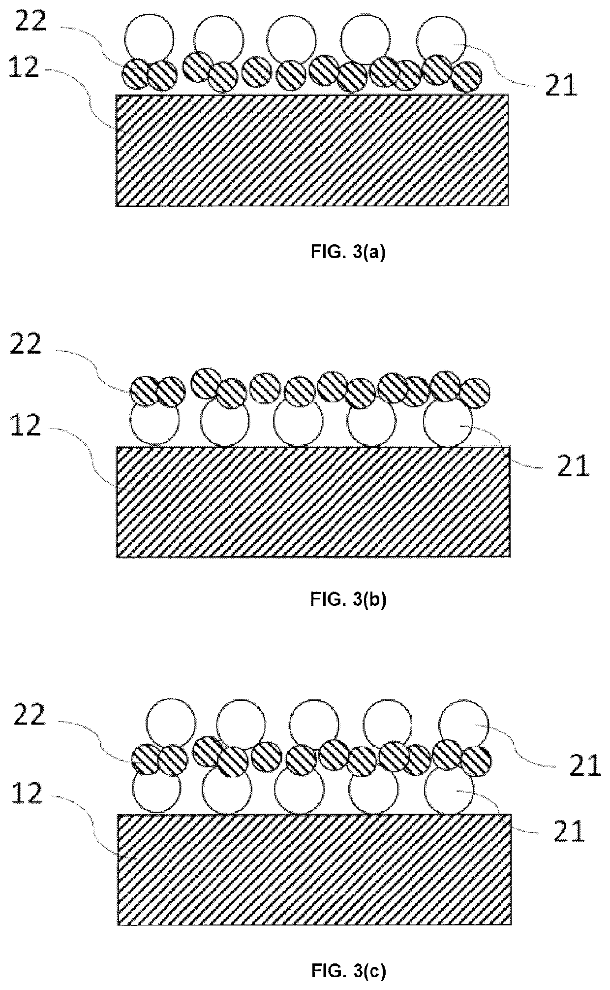
Figure 3
Abstract
Description
FIELD OF THE INVENTION
[0001] The present invention relates to a honeycomb structure and an exhaust gas purifying device. More particularly, the present invention relates to a honeycomb structure and an exhaust gas purifying device, which have an improved combustion efficiency of carbon particulates and the like due to induction heating and have a suppressed increase in pressure loss.BACKGROUND OF THE INVENTION
[0002] There is an increased need for reduction of harmful components (HC, NOx, CO) in automobile exhaust gas. At present, the harmful components to be discharged are discharged during a period immediately after starting an engine, i.e., a period during which a catalyst temperature is lower and an activity of the catalyst is insufficient. To address this problem, Patent Literature 1 discloses a technique for inserting a magnetic wire into a part of cells of a cordierite honeycomb which is widely used as a catalyst supported honeycomb, and passing an electric current through a coi...
Examples
Embodiment Construction
[0029]Hereinafter, embodiments of a honeycomb structure according to the present invention will be described with reference to the drawing. However, the present invention is not limited to these embodiments, and various changes, modifications, and improvements may be made based on knowledge of those skilled in the art, without departing from the scope of the present invention.
[0030]FIG. 1 is a perspective view schematically showing a honeycomb structure 1 according to an embodiment of the present invention. The illustrated honeycomb structure 1 is pillar-shaped and has an outer peripheral wall 11 located on the outermost circumference. Further, the illustrated honeycomb structure 1 has the porous partition walls 12 which are arranged inside the outer peripheral wall 11 and define a plurality of cells 15 that penetrate from one end face 13 to the other end face 14 to form flow paths.
[0031]Although materials of the partition walls 12 and the outer peripheral wall 11 of the honeycomb s...