
Vapor-adsorbent filter for reducing evaporative fuel emissions, and method of using same
a technology of evaporative fuel and filter, which is applied in the direction of filtration separation, combustion-air/fuel-air treatment, separation process, etc., can solve the problems of contributing to air pollution
Patent Information
- Authority / Receiving Office
- US · United States
- Patent Type
- Patents(United States)
- Current Assignee / Owner
- Publication Date
- 2002-08-13
- Estimated Expiration
- Not applicable · inactive patent
Smart Images
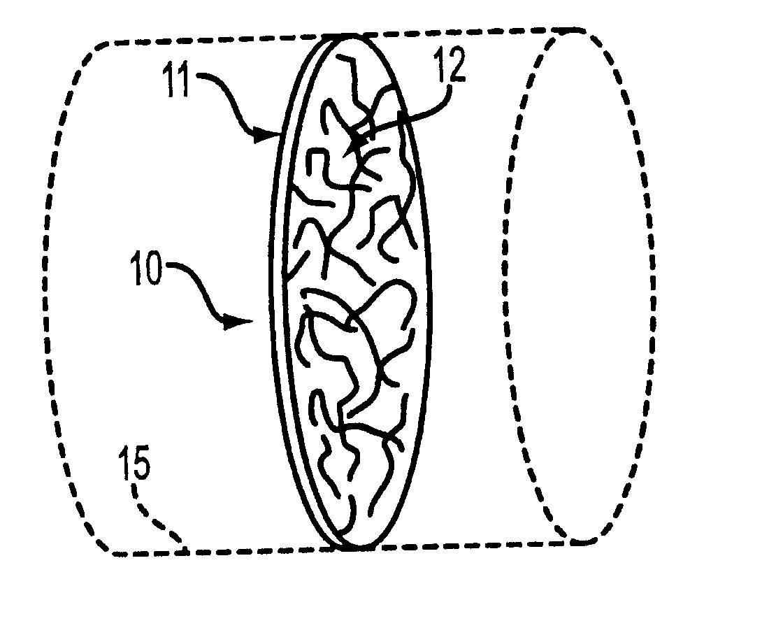
Figure 1 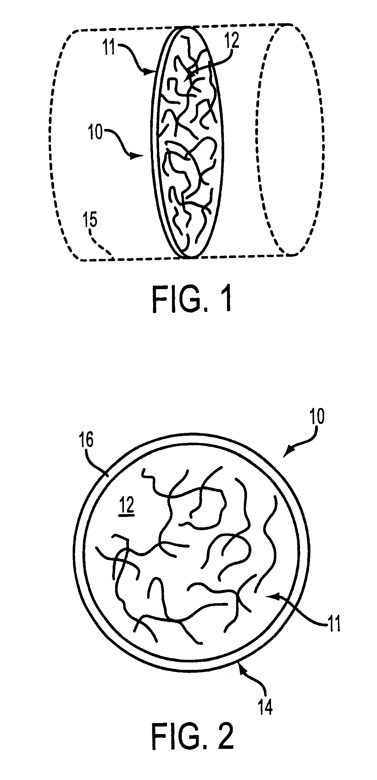
Figure 2 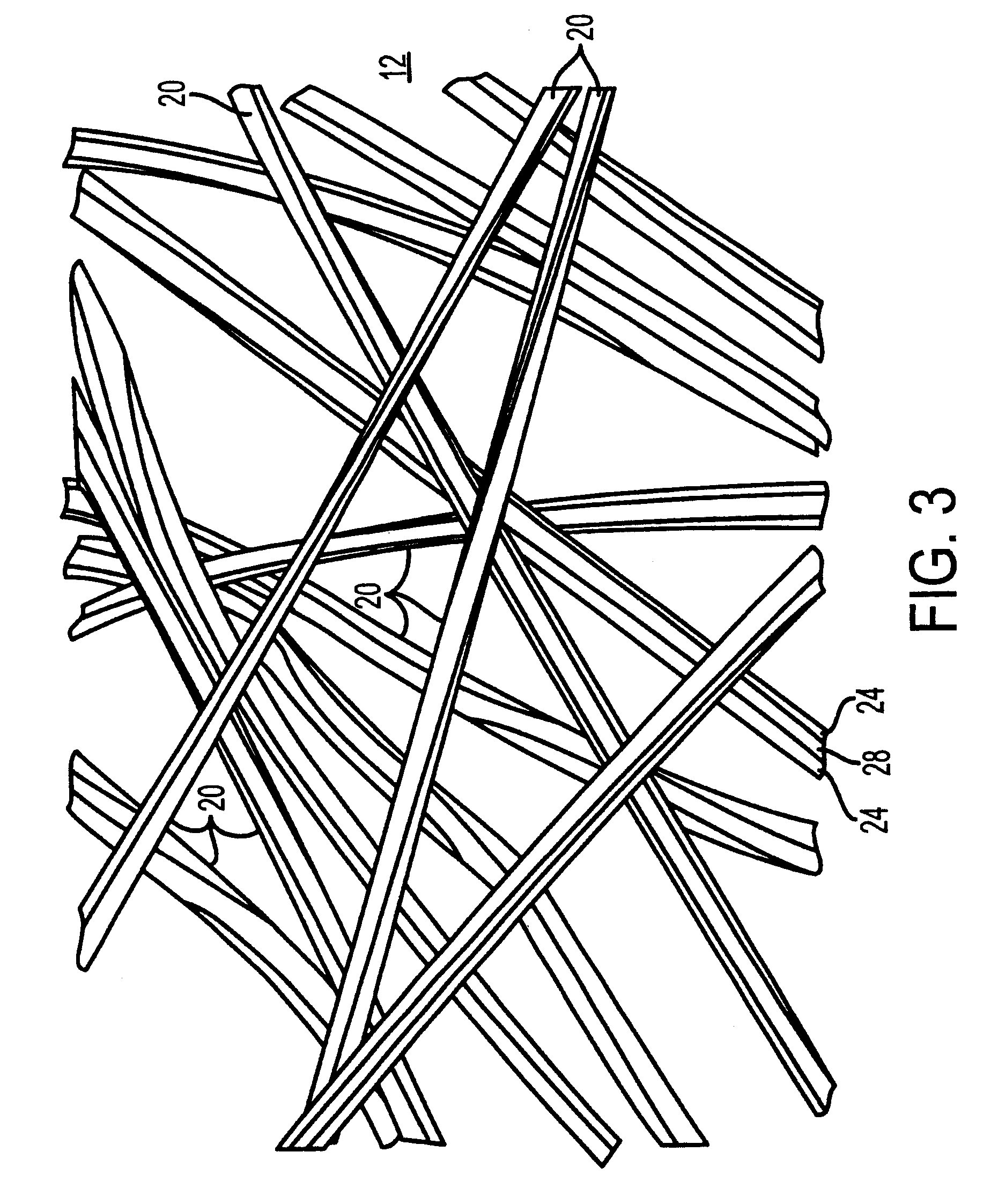
Figure 3
Abstract
Description
1. Field of the inventionThe present invention relates to a filter for reducing evaporative fuel emissions from an internal combustion engine. More particularly, the present invention relates to a filter for placement on an engine, downstream of a throttle plate, to adsorb evaporative emissions after the engine has been turned off.2. Description of the Background ArtThe great majority of internal combustion engines in use today are fuel-injected engines. When a fuel-injected engine is switched off after use, a small amount of residual fuel volatilizes and escapes from the injector tips. While a vehicle is sitting over time after use, this evaporated fuel may pass outwardly through the intake manifold, the intake air ducts and air filter, and may escape into the atmosphere, thus contributing to air pollution. It would be desirable to minimize this type of inadvertent evaporative emissions leakage.Many different types of filters are known for use in filtering evaporative fuel emission...
Examples
first embodiment
Referring now to FIGS. 1-7, a filter in accordance with the invention is shown generally at 10. The filter 10 is provided for placement in an intake airflow passage 15, associated with an internal combustion engine (not shown). The airflow passage 15 does not form a part, per se, of the present invention. The filter 10 may be placed extending across a flow passage such as, for example, a portion of an intake manifold or a throttle body.
The filter 10 includes a filter element 11, which comprises a porous non-woven fiber web 12 made up of a plurality of individual fibers 20 (FIG. 3). In the filter element 11, the fiber web 12 is preferred to be made in a loose weave with relatively large air pockets between the fibers, in order to minimize pressure drop thereacross.
The pressure drop across the filter 10 is less than 5 inches of mercury at 5,000 cubic feet per minute of flow. Preferably, the pressure drop is less than 3 inches of mercury at 5,000 cubic feet per minute of flow.
Optionall...
second embodiment
Referring now to FIG. 8, another embodiment of a filter 210 is shown in accordance with a second embodiment of the invention. In the illustration, a throttle plate 202 is shown disposed within an intake air flow passage 215 of a throttle body 205, which is shown in phantom for purposes of illustration. The throttle plate 202 is generally conventional, and does not form a part of the present invention.
A circular disc-shaped filter element 211, in accordance with a second embodiment of the present invention, is affixed to the rear surface of the throttle plate 202. The filter element 211 may be glued on, or otherwised attached to the throttle body in conventional fashion.
The filter element 211 includes a porous non-woven fiber web 212 made up of a plurality of individual fibers 20. The fibers 20 making up the filter element 211 are the same as previously discussed in connection with the first embodiment.
The fibers 20 are impregnated with a fuel vapor-adsorbing compound, as discussed h...
third embodiment
Referring now to FIG. 9, another filter assembly 310 is shown, in accordance with a third embodiment of the invention. In the embodiment of FIG. 9, a pair of semi-circular opposed baffle plates 302, 304 are provided for placement in an intake air flow passage 315, associated with an internal combustion engine (not shown). The filter assembly 310 may be placed in a flow passage 315 such as, for example, a portion of an intake manifold.
These baffle plates 302, 304 may be made foraminous or solid, according to the application. The baffle plates 302, 304 are each pivotally mounted in the air flow passage 315, so as to be movable between a horizontal, open position when the engine is running, and a vertical, closed position when the engine is off.
The filter 310 also includes a pair of filter elements 306, 308, made in the same semi-circular D-shape as the baffle plates, and attached to the back surface thereof by any appropriate method. Each of the filter elements includes a porous nonwo...