
Snowplowable pavement marker
Patent Information
- Authority / Receiving Office
- US · United States
- Current Assignee / Owner
- Publication Date
- 2002-08-27
- Estimated Expiration
- Not applicable · inactive patent
Smart Images
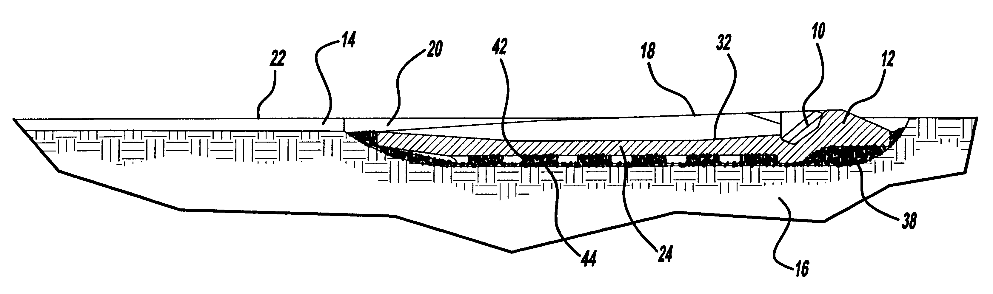
Figure 1 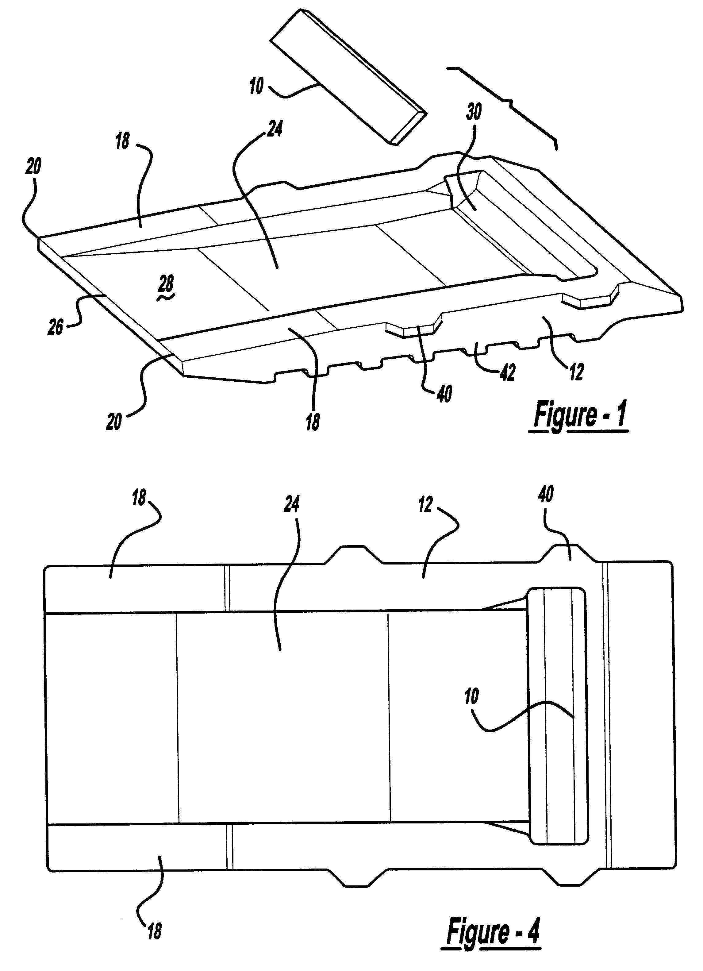
Figure 2 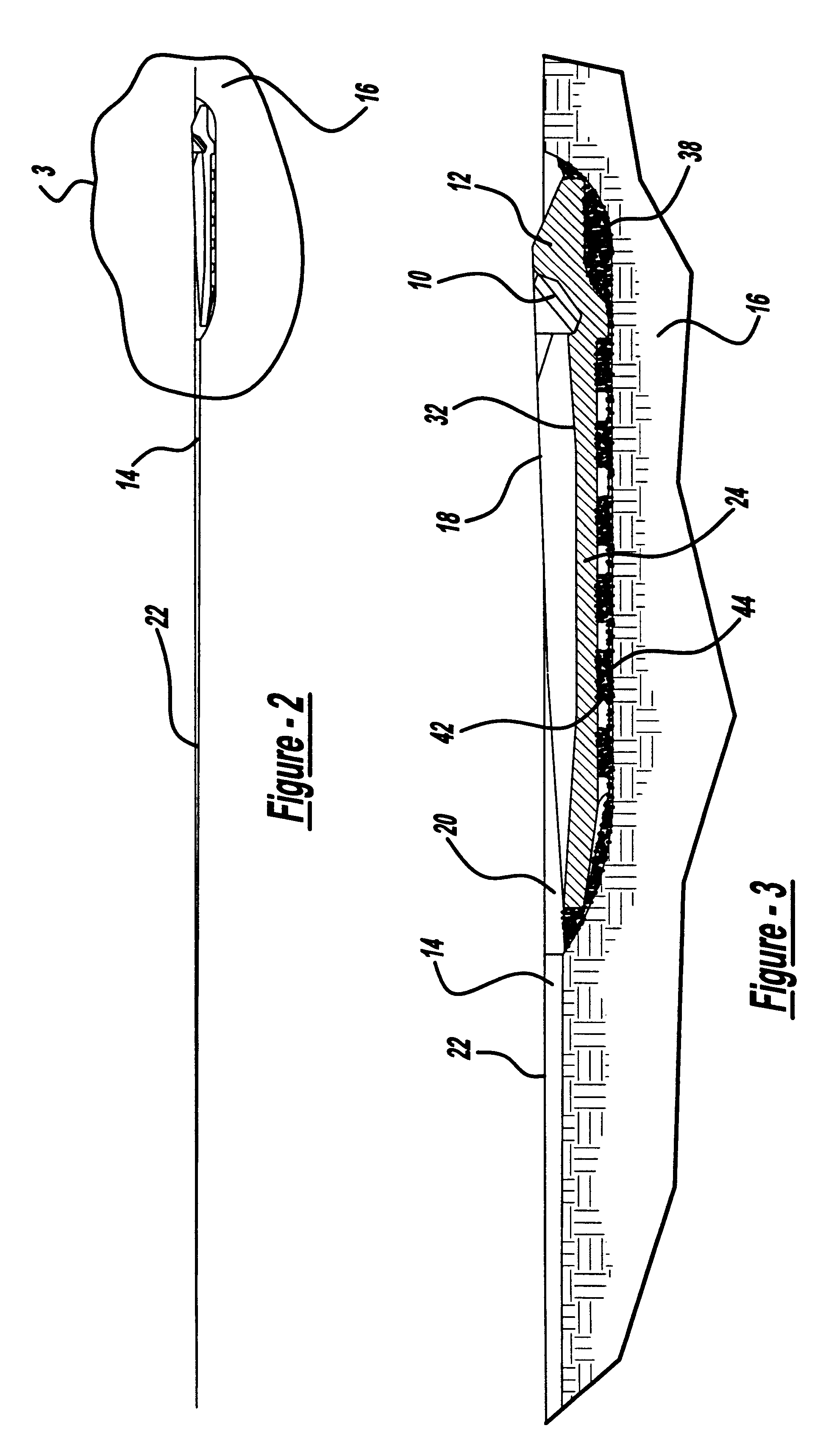
Figure 3
Abstract
Description
The present invention relates to pavement markers which are recessed into the pavement surface. The pavement marker is designed for use in areas that receive snowfall and hence, is designed to be snowplowable while resistant to damage from the action of the snowplow.SUMMARY OF THE PRIOR ARTPavement markers, as used herein, are mechanisms for setting a reflective element in or on the roadbed so that the light of the vehicle headlamps can be reflected back to the driver. The source of the reflection delineates edges of lanes, on / off ramps, and other features of the roadbed. These pavement markers are used in addition to, or instead of, standard paint, epoxy, or thermoplastic striping.Pavement markers are generally broken down into two types--sun country or snowplowable. Sun country markers are used where snow is either not present or an infrequent event, and thus their design does not have to take into account the operation of a snowplow to clear the traffic lanes. Snowplowable marker...
Examples
Embodiment Construction
The present invention has a reflector 10 mounted in a base 12 to reflect light from the headlamps of a vehicle back to the driver of the vehicle. Reflector or retroreflector as used herein can be a plastic, glass or composite material designed to reflect the light from oncoming headlamps back to the driver. Prior art metallized lens can also be used. For examples of reflectors, see Balint, U.S. Pat. No. 3,409,344 which discloses acrylic lens elements in an ABS housing. Another example of a retroreflector element is shown in Flanagan, U.S. Pat. No. 4,498,733. Various models of reflectors known to those in the art can be used such as Stimsonite Model 944 retroreflector, available in the trade or 3M model #194 of retroreflector.
As shown in FIG. 2, the present marker is designed to be placed in a groove 14 cut in the pavement 16. The groove is several times the length of the marker. The length of the groove is determined in part by the need for light to travel in the groove to impinge o...