
Automated machine and method for fruit testing
Patent Information
- Authority / Receiving Office
- US · United States
- Current Assignee / Owner
- Publication Date
- 2003-11-04
- Estimated Expiration
- Not applicable · inactive patent
Smart Images
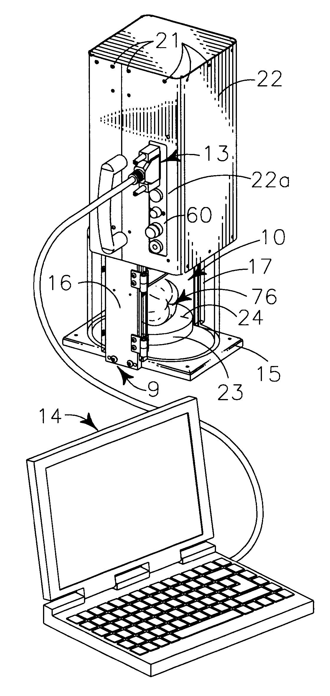
Figure 1 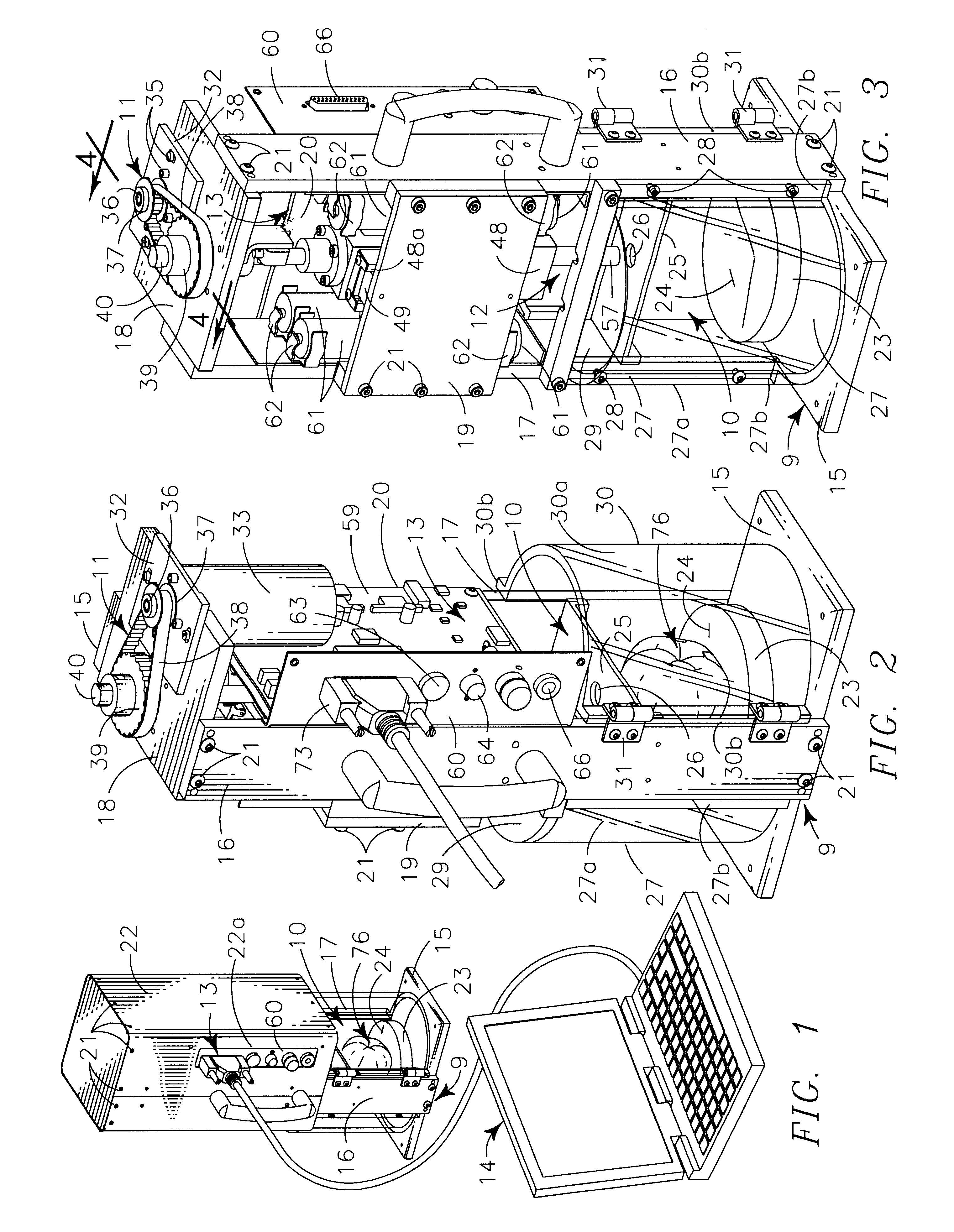
Figure 2 
Figure 3
Abstract
Description
II. BACKGROUND OF INVENTIONIIA. RELATED APPLICATIONSThere are no applications related hereto heretofore filed in this or any foreign country.1. Field of InventionOur invention relates generally to measuring and testing, and more particularly to a mechanized penetration type tester that is computer operated and serviced for such testing and processes for fruit testing allowed by the tester.2. Background and Description of Prior ArtThe determination of the ripeness and the maturational state of fruit has been a human desire probably as long as fruit has been used as a food product. Through the history of such determinations the process has devolved from subjective tastable, visual and manual inspection to mechanized and sophisticated somewhat objective procedures, but substantial problems still remain to be resolved to provide meaningful objectivity. The instant invention seeks to solve or alleviate various of these remaining problems, especially as they relate to softer fruits of the...
Examples
Embodiment Construction
Our tester generally comprises frame 9 enclosing testing chamber 10 in its lower portion and carrying powering train 11 to move plunger structure 12 within the testing chamber to operatively engage fruit 76 positioned within the testing chamber. Control member 13 carried by the frame 9 receives software generated control data from associated computer 14 to operate the powering train and senses, receives and transmits process data to the computer for analysis, displays and recordation.
Frame 9 provides rectilinear base 15 supporting elongate upwardly extending left side 16 and peripherally similar right side 17 in parallel lateral alignment on the elongately medial portion of the base. Top 18 is structurally carried between the upper portions of the right and left sides 16 and 17. Back plate 19 is carried on the rearward facing edges of the sides 16, 17 in their medially upper portions. Forward circuitry support panel 20 is carried on the forward edges of sides 16, 17 in their mediall...