
Multi-row cam-actuated centrifugal clutch
a centrifugal clutch and cam-actuated technology, which is applied in the direction of mechanical actuated clutches, friction clutches, clutches, etc., can solve the problems of insufficient centrifugal force generated to clamp the clutch plates together without substantial slipping or withou
Patent Information
- Authority / Receiving Office
- US · United States
- Patent Type
- Patents(United States)
- Current Assignee / Owner
- Publication Date
- 2004-11-09
- Estimated Expiration
- Not applicable · inactive patent
Smart Images
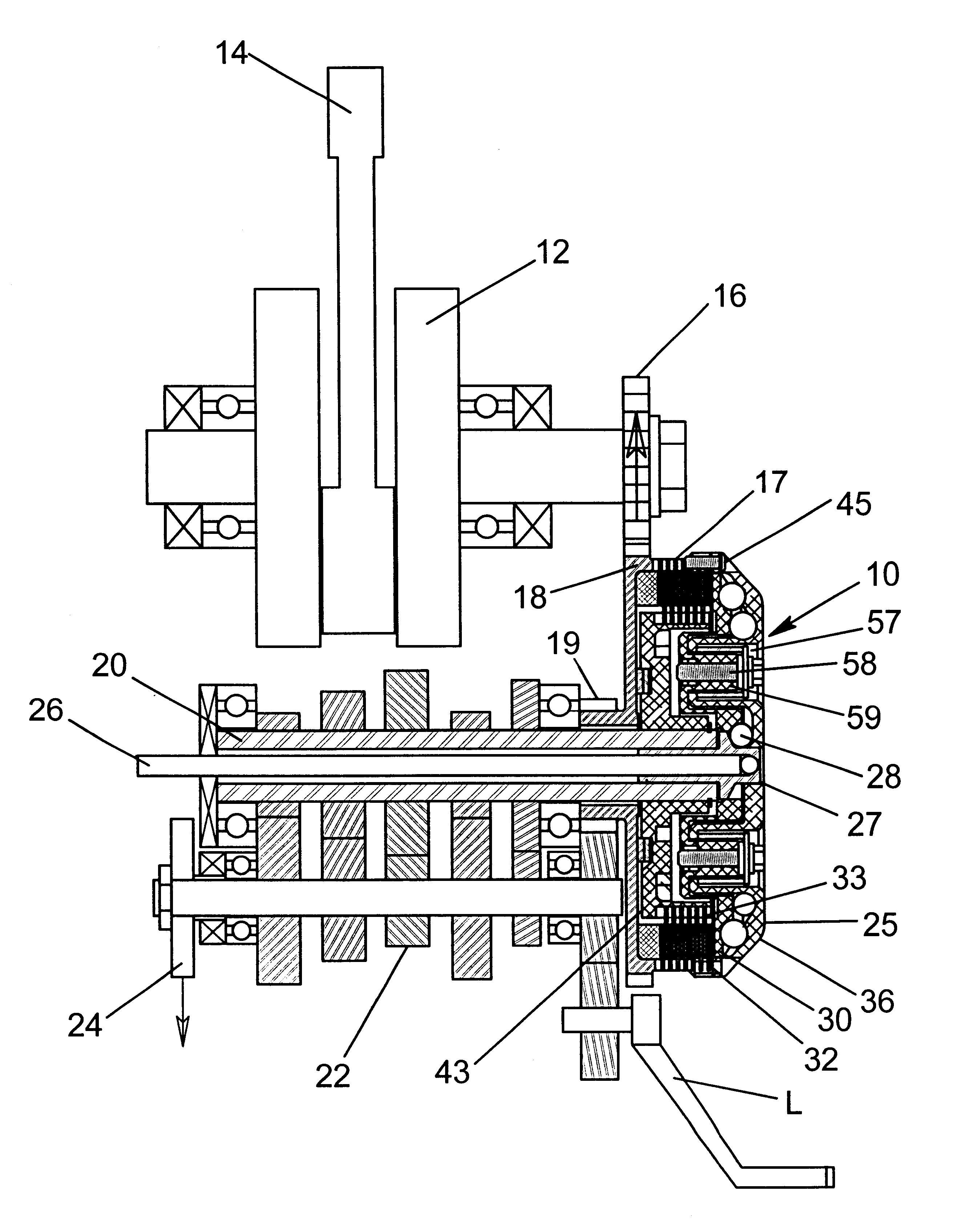
Figure 1 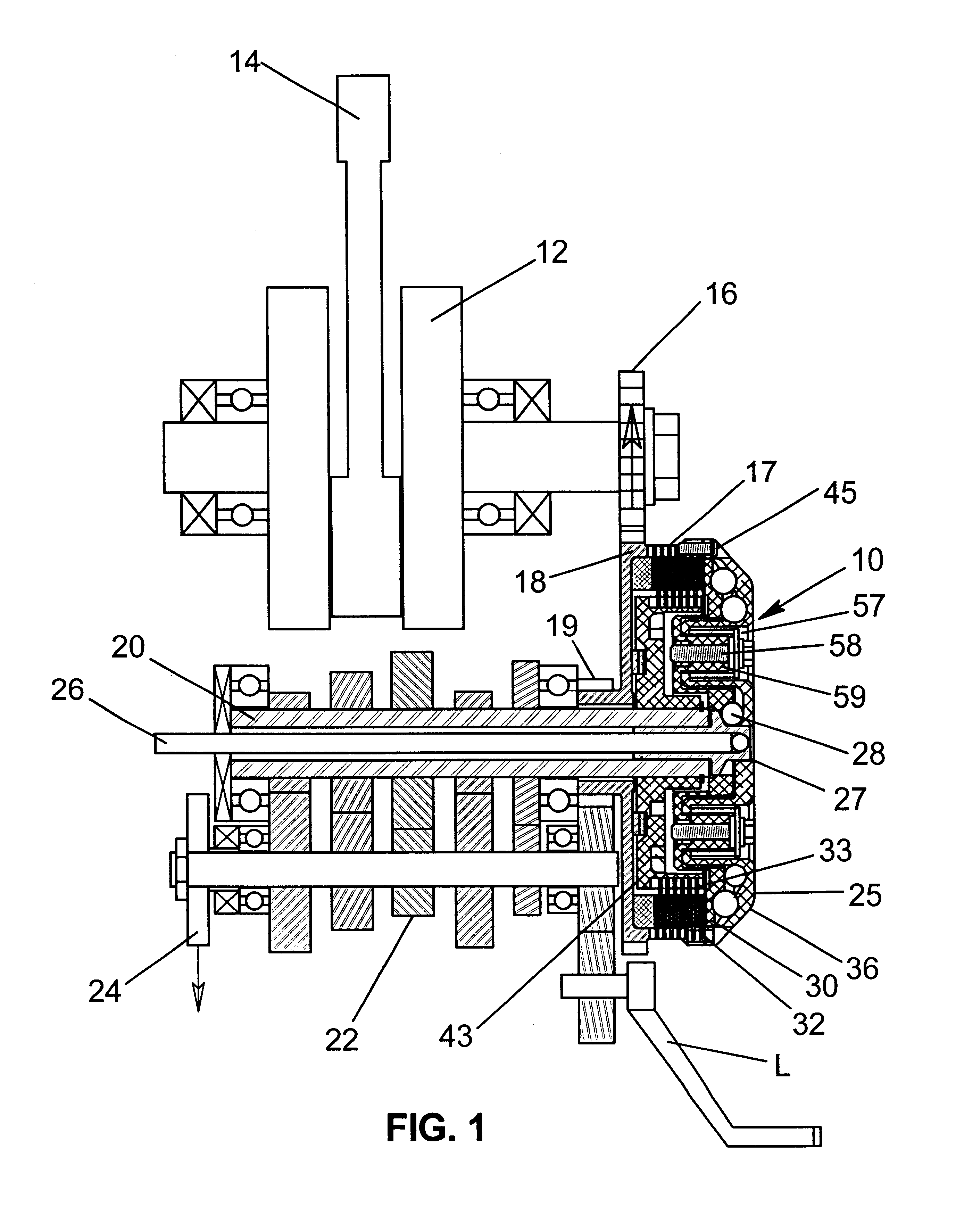
Figure 2 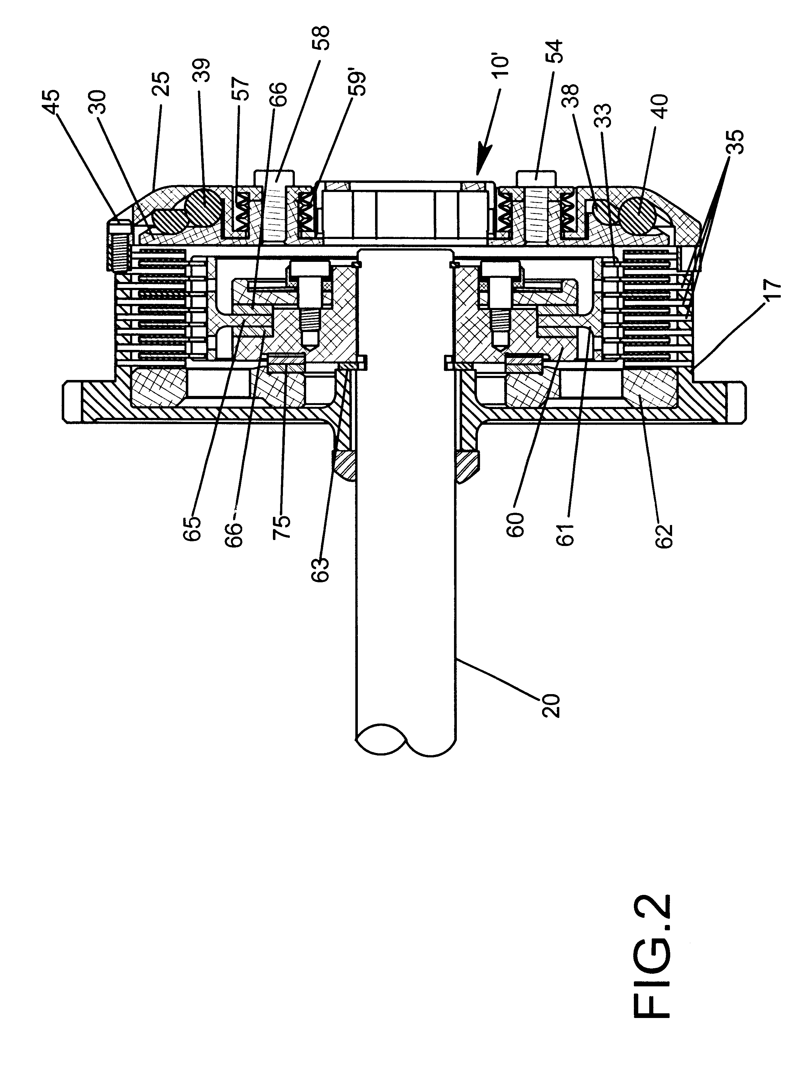
Figure 3
Abstract
Description
BACKGROUND AND FIELD OF INVENTIONThis invention relates to centrifugal clutches and more particularly relates to novel and improved centrifugal clutches having high density cam members which are urged outwardly under centrifugal force in order to activate the clutching elements.Centrifugal clutches have been developed for motorcycles utilizing one or two rows of balls or other cam members which would move outwardly in response to rotation of a drive shaft to cause the clutch plates to move into engagement with one another. However, in certain applications it was found that there is insufficient centrifugal force generated to clamp the clutch plates together without substantial slipping or without utilizing a larger size case or cover which exceeds the space allowances within stock engine cases. For example, space is at a particular premium in motorcycle clutches incorporating a manual override mechanism, such as, that set forth and described in copending application for U.S. patent ...
Examples
Embodiment Construction
FIGS. 2 to 11 illustrate a preferred form of clutch 10' in which like parts to those of FIG. 1 are correspondingly enumerated. More specifically, in FIGS. 2 and 3, the manual override mechanism in FIG. 1 consisting of the push rod 26, slide 27 and cams 28 has been removed. Instead, the clutch is actuated only by the cam-actuating mechanism 36 which is broadly comprised of radially inner and outer rows of circumferentially spaced cam members or bails 38, 39 and 40 interposed between a pressure plate 30 and a cover 25. The balls 38 to 40 are responsive to centrifugal force to roil outwardly along radial pockets or cam faces 48, 52 and 56 in the pressure plate 30 and aligned pockets or cam faces 46, 50 and 54 in the cover 25 so as to axially displace the outer frictional clutch plates 32 into locking engagement with the inner clutch plates 34.
An important feature of the present invention resides in the radially inner and outer rows of cam members or balls 38, 39 and 40. Preferably, as ...