
Apparatus and method for preventing an overshoot in the rotation speed of an internal-combustion engine
Patent Information
- Authority / Receiving Office
- US · United States
- Current Assignee / Owner
- Publication Date
- 2005-10-25
Smart Images
Figure 1 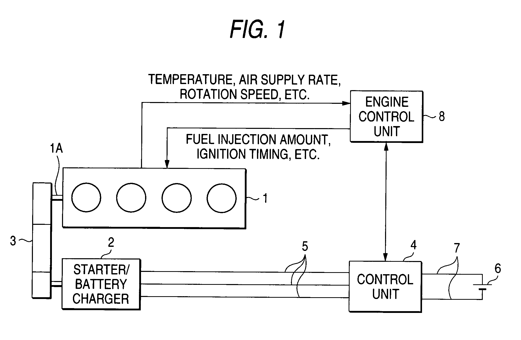
Figure 2 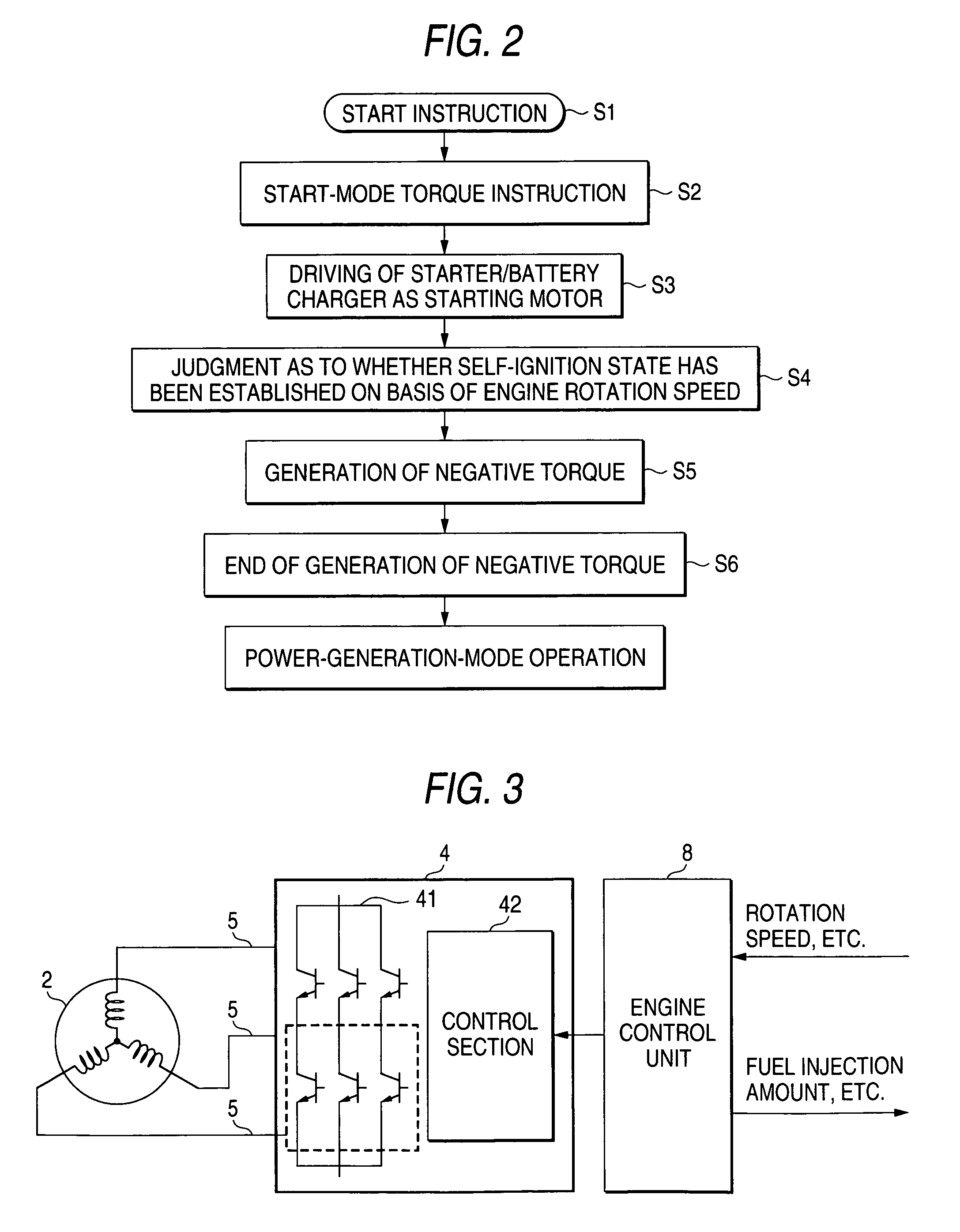
Figure 3
Abstract
Description
BACKGROUND OF THE INVENTION
[0001] 1. Field of the Invention
[0002] The present invention relates to an apparatus and method for preventing an overshoot in the rotation speed of an internal-combustion engine.
[0003] 2. Description of the Related Art
[0004] It is well known that an internal-combustion engine is started by rotating the crank shaft of the engine by means of a starter that is coupled to the engine. In general, the rotation speed of an internal-combustion engine is increased to 200 to 300 rpm at the time of a start and is thereafter increased further to a self-ignition rotation speed of the engine, that is, an idling rotation speed or a rotation speed of a control by a controller for the engine.
[0005] In starting an internal-combustion engine, to improve the ignition performance in a range lower than an idling rotation speed, the controller for the engine performs a control of promoting a self-ignition-based operation by controlling the ignition timing and increasing a fuel suppl...
Examples
first embodiment
[0024]A first embodiment of the present invention will be described below with reference to FIG. 1. FIG. 1 is a schematic diagram showing a configuration and a method of the first embodiment. As shown in FIG. 1, a starter / battery charger 2 of an internal-combustion engine 1 is a 3-phase synchronous rotary machine, for example, which is coupled to a crank shaft 1A of the engine 1 via a belt 3. Alternatively, the starter / battery charger 2 may be coupled to the crank shaft 1A directly, that is, without intervention of the belt 3.
[0025]A control unit 4 for the starter / battery charger 2 is connected to the starter / battery charger 2 via 3-phase lines 5 that are connected to 3-phase armature coils, and controls the starter / battery charger 2 so that it can generate start drive torque (positive torque) or braking torque (negative torque).
[0026]A battery 6 that is connected to the control unit 4 via power lines 7 serves as a power source for the control unit 4. When the starter / battery charge...
second embodiment
[0032]Next, a second embodiment of the invention will be described with reference to FIG. 3. FIG. 3 is a schematic diagram showing a starter / battery charger and its control unit according to the second embodiment. Components in FIG. 3 having the same or corresponding components in FIG. 1 are given the same reference numerals and will not be described.
[0033]The control unit 4 for the starter / battery charger 2 includes an inverter section 41 consisting of arms of three respective phases in each of which a pair of switching elements are connected to each other in series. The control unit 4 also includes a control section 42 of the inverter section 41. The control unit 4 controls the supply of power to the starter / battery charger 2 on the basis of an instruction from the higher-rank control unit or the engine control unit 8. On the other hand, monitoring the rotation speed of the engine 1, the higher-rank control unit or the engine control unit 8 judges, in the above-described manner, o...
third embodiment
[0035]Next, a third embodiment of the invention will be described with reference to FIG. 4. FIG. 4 is a schematic diagram showing a starter / battery charger and its control unit according to the third embodiment. Components in FIG. 4 having the same or corresponding components in FIG. 3 are given the same reference numerals and will not be described. This embodiment is different from the second embodiment of FIG. 3 in the following points. Switches 91 and 92 are provided between the armature 3-phase lines 5 for the 3-phase armature coils of the starter / battery charger 2. The switches 91 and 92 are closed in response to the engine self-ignition completion signal from the higher-rank control unit or the engine control unit 8 and a 3-phase short-circuited state is established for a prescribed time, during which the starter / battery charger 2 generates negative torque. This makes it possible to properly prevent the overshoot in the rotation speed of the engine 1.
[0036]In this embodiment, ...