
Prosthetic annular coupling socket adaptor with adjustable clamp
Patent Information
- Authority / Receiving Office
- US · United States
- Current Assignee / Owner
- Publication Date
- 2006-02-07
- Estimated Expiration
- Not applicable · inactive patent
Smart Images
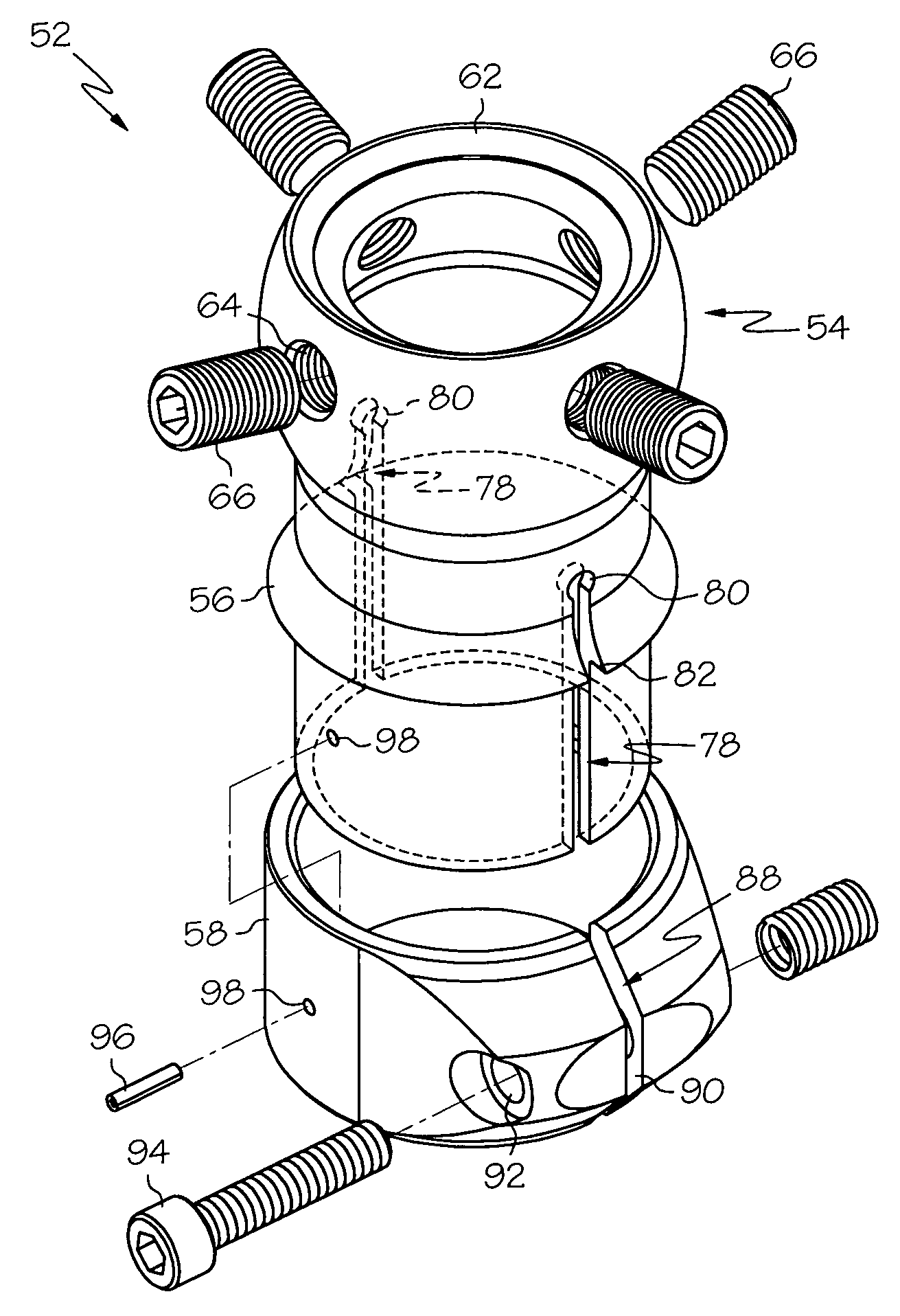
Figure 1 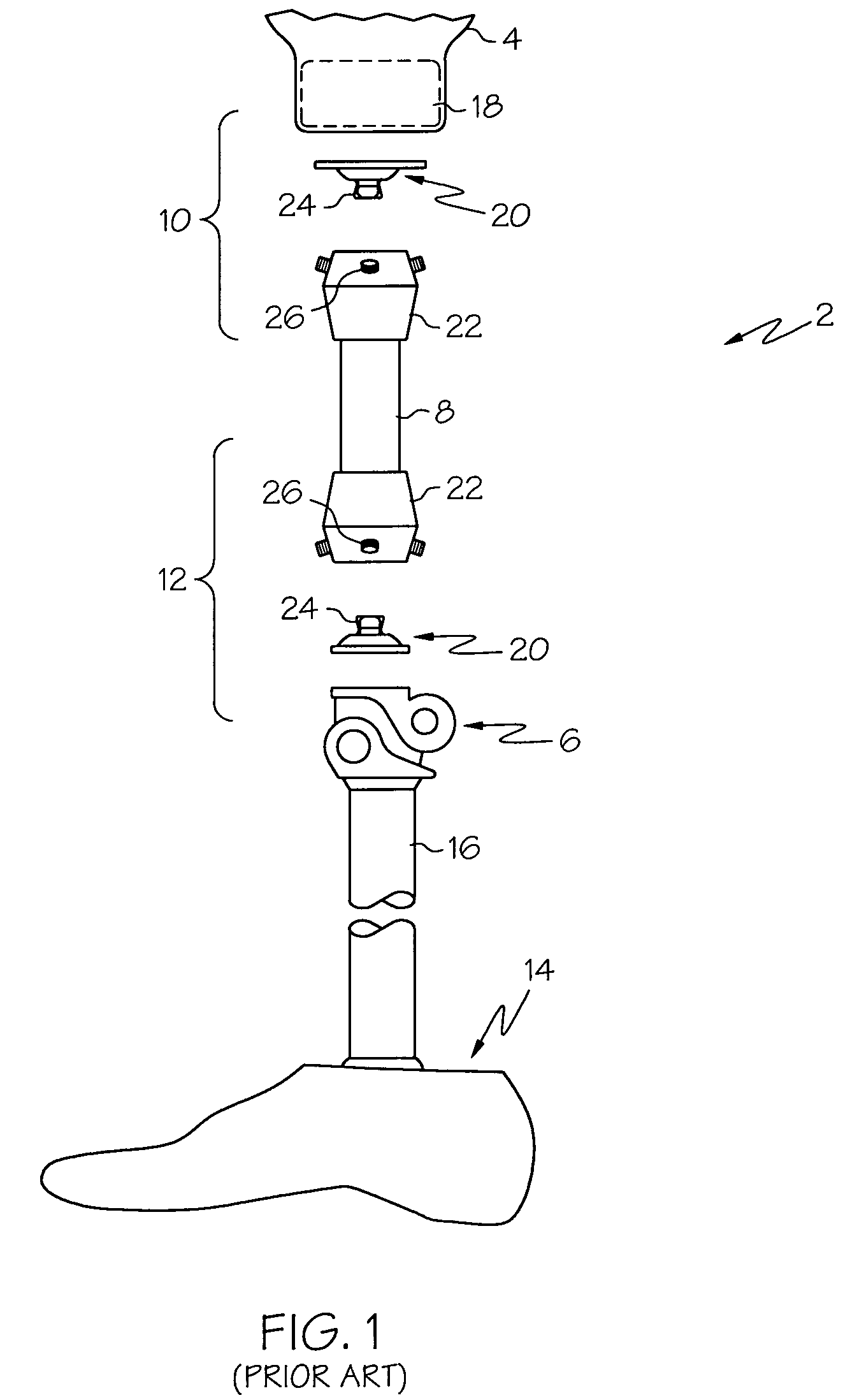
Figure 2 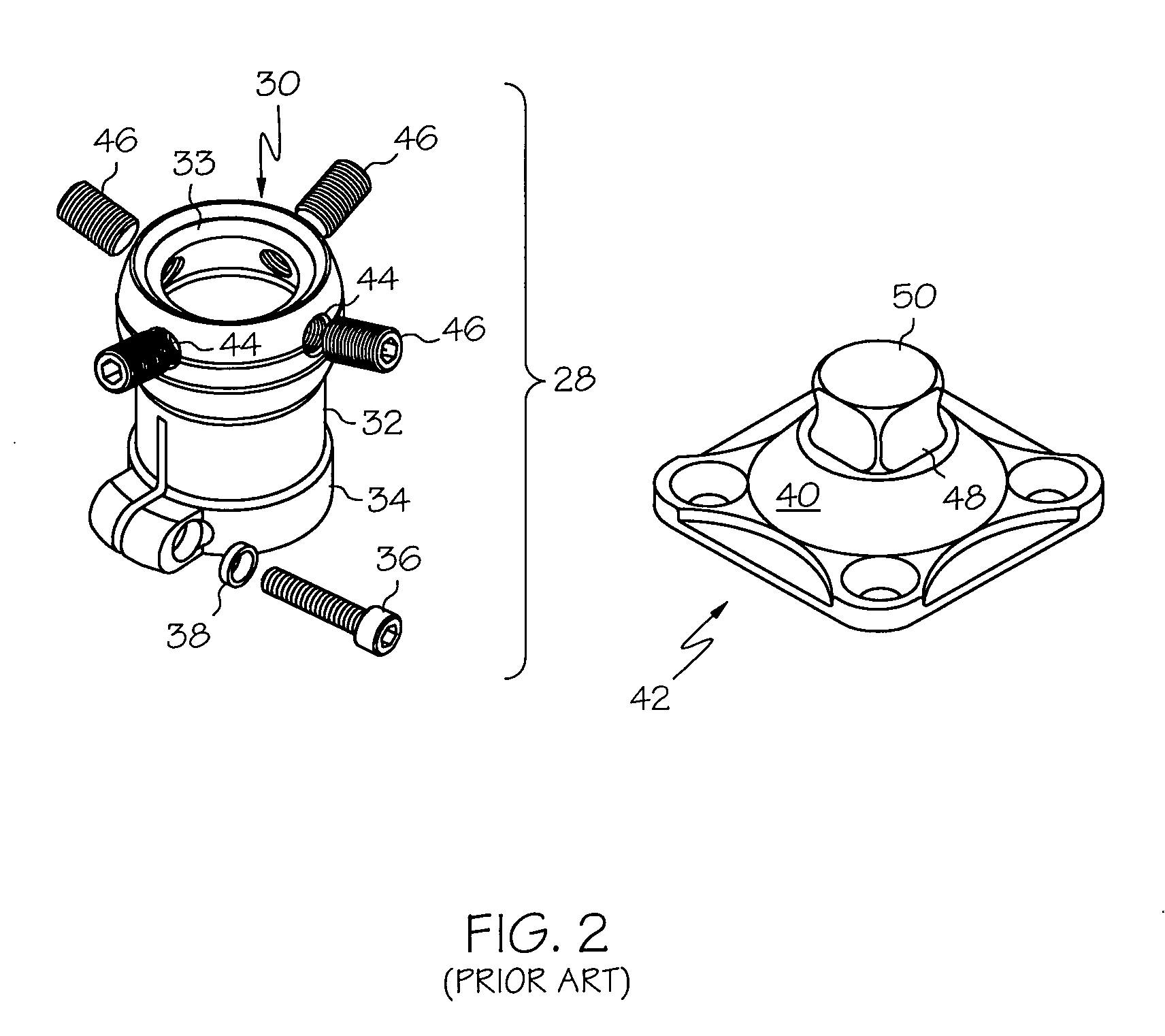
Figure 3
Abstract
Description
CROSS REFERENCE TO RELATED APPLICATION
[0001] This application claims the benefit of U.S. Provisional Application Ser. No. 60 / 361,427, entitled, “PROSTHETIC ANNULAR COUPLING SOCKET ADAPTOR WITH ADJUSTABLE CLAMP”, filed on Feb. 28, 2002, the disclosure of which is incorporated herein by reference.BACKGROUND
[0002] 1. Field of the Invention
[0003] The present invention relates to prosthetic devices, and more particularly, to prosthetic couplings having annular coupling socket adapters (aka, “pyramid receivers”) with adjustable height tube clamps.
[0004] 2. Description of the Related Art
[0005] As shown in FIG. 1, an example of an above-knee (“AK”) prosthetic limb 2 for a patient may include a prosthetic limb socket 4 for receiving the wearer's residual limb, a knee joint assembly 6, a first pylon 8 coupled between the prosthetic limb socket 4 and the knee joint assembly 6, interconnection components 10 for coupling the first pylon 8 to the prosthetic limb socket 4, interconnection components 12...
Examples
Embodiment Construction
[0024]The exemplary embodiments of the present invention are described and illustrated below as prosthetic limb couplings, for mounting a first prosthetic component to a second pylon component, that include height-adjustable tube clamps for mating with pylon components. The various orientational or positional terms used to describe the elements of the inventions are therefore used according to this frame of reference. Of course, it will be apparent to those of ordinary skill in the art that the preferred embodiments may also be used in combination with one or more prosthetic components to function as a complete prosthetic assembly. In such a case, the orientational or positional terms may be different. However, for clarity and precision, only a single orientational or positional reference will be utilized; and, therefore it will be understood that the positional and orientational terms used to describe the elements of the exemplary embodiments of the present invention are only used ...