
Cushioning pads and the formation of cushioning pads
Patent Information
- Authority / Receiving Office
- US · United States
- Current Assignee / Owner
- Publication Date
- 2006-03-07
- Estimated Expiration
- Not applicable · inactive patent
Smart Images
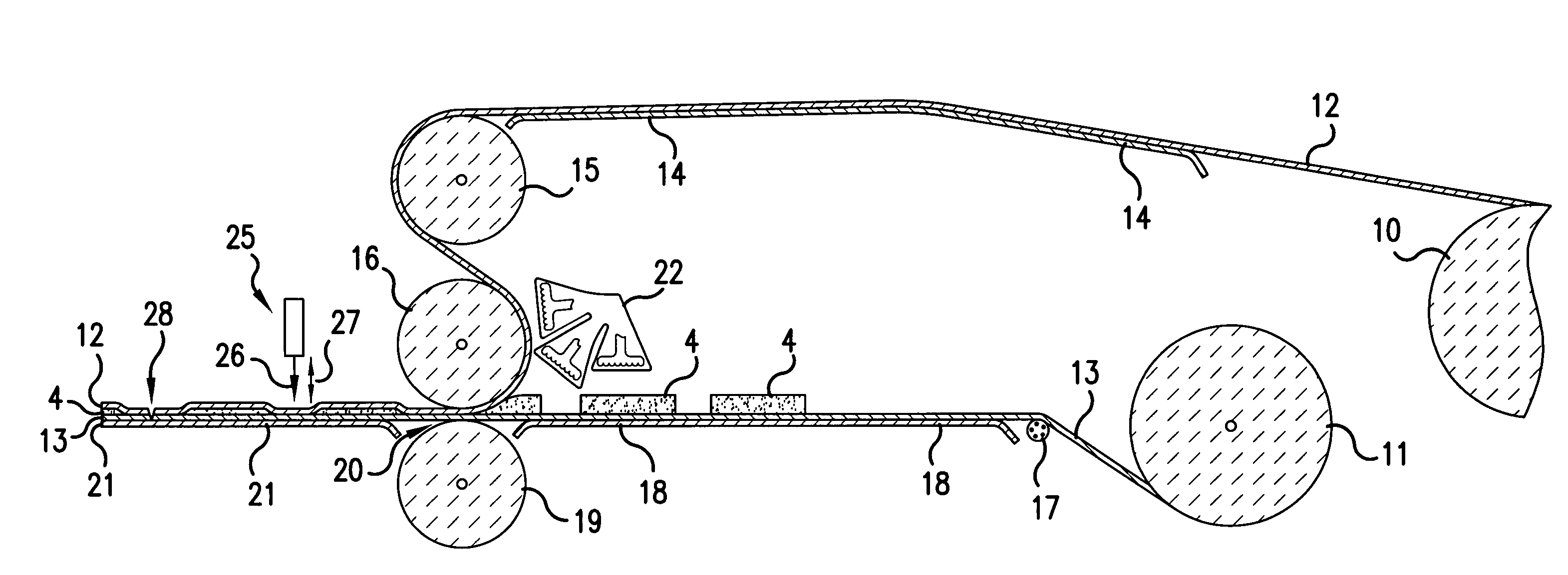
Figure 1 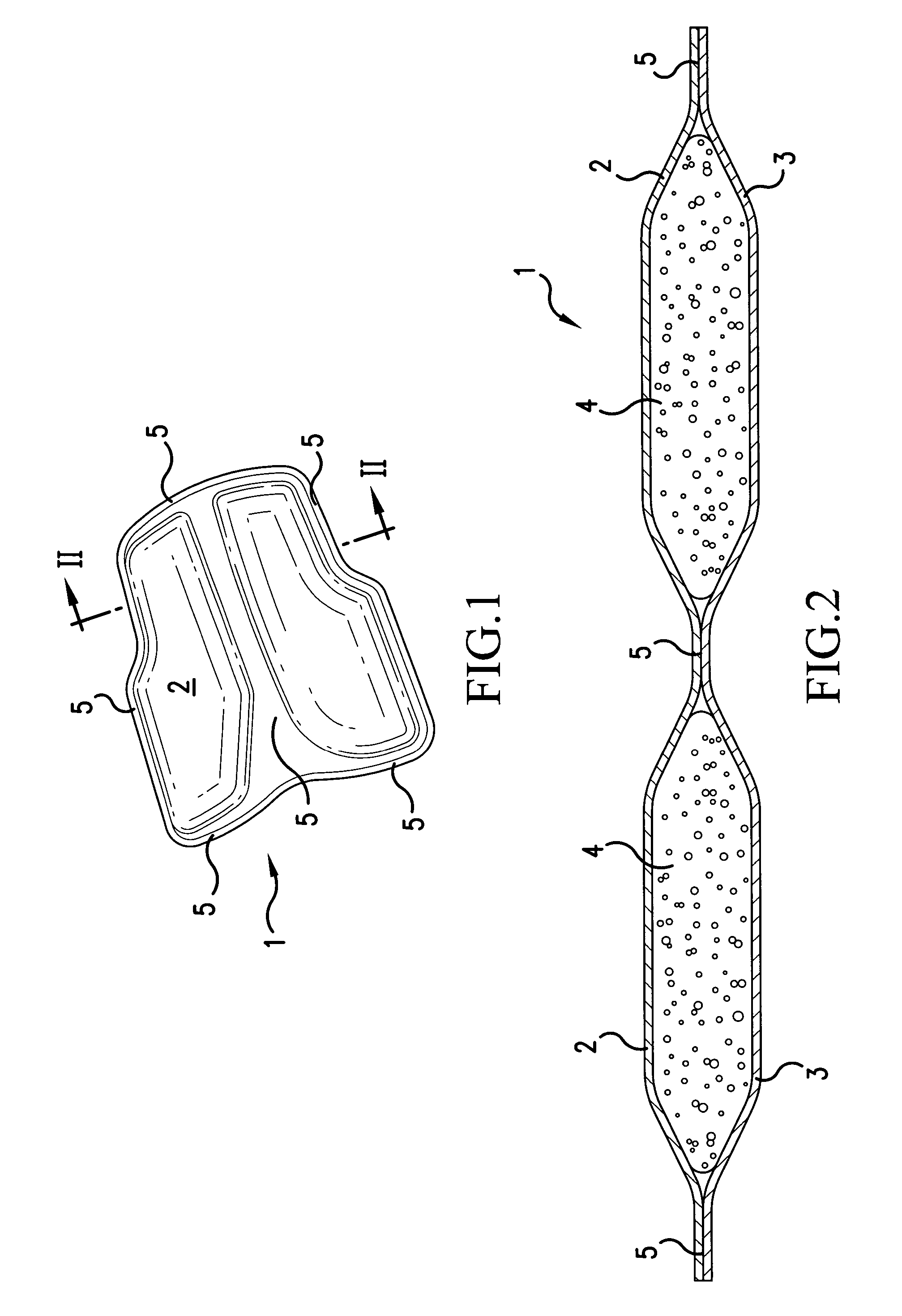
Figure 2 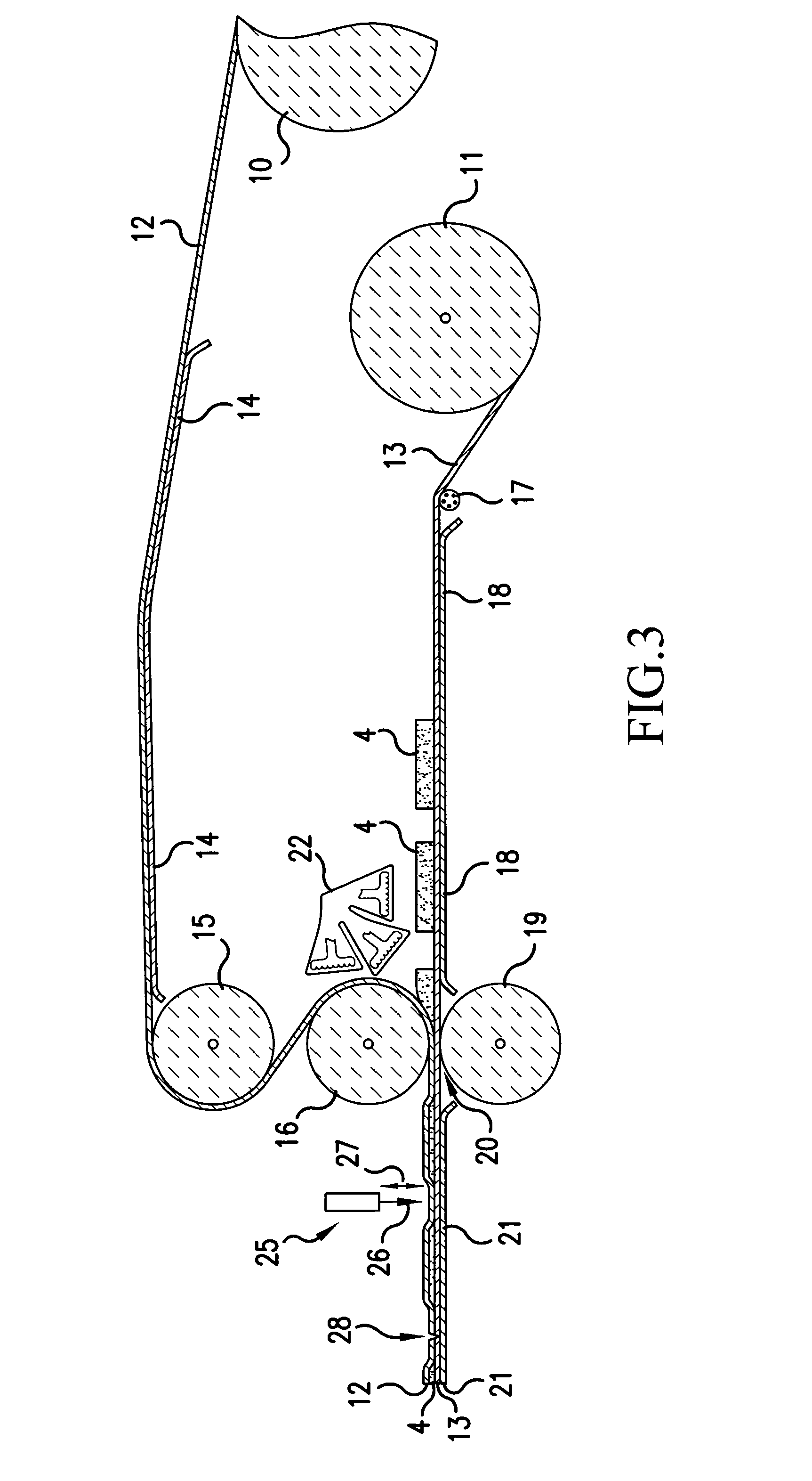
Figure 3
Abstract
Description
[0001] This is a continuation of application Ser. No. 09 / 335,987, filed Jun. 18, 1999, now abandoned, the entire contents of which are hereby incorporated by reference.BACKGROUND OF THE INVENTION
[0002] 1. Field of the Invention
[0003] The present invention relates to a method of forming a cushioning pad, and several cushioning pads produced by the method.
[0004] 2. Description of the Related Art
[0005] Cushioning pads, or impact absorbing pads, are well known in the existing art. Impact absorbing pads are used to improve the comfort and ergonomics of many items which interact with humans and animals. Also, impact absorbing pads are useful in dampening vibrations and deadening sound between interacting objects. Typical applications for these pads include sporting gear apparel, seat covers, and shoe insoles and linings.
[0006] Typical impact absorbing pads are constructed of a resilient layer of an open-air material, such as foam or polyurethane. The resilient layer is porous and naturally hold...
Examples
Embodiment Construction
[0030]FIGS. 1 and 2 illustrate a pad 1 constructed by a method in accordance with the present invention. The pad 1 includes a first layer 2 of a first material and a second layer 3 of a second material. The first layer 2 is attached to the second layer 3 at seamed sections 5 to encapsulate one or more components 4.
[0031]The first and second materials are preferably a flexible resilient material which has a low permeability to air, such as a closed-cell foam, like polyethylene foam. The third material is preferably a flexible resilient material which can absorb and release air, such as an open-celled, foam like polyurethane foam. Such open-cell foam typically contains approximately 80% air by volume when in an uncompressed state.
[0032]FIG. 3 is a cross sectional view illustrating an apparatus for, and a method of, forming the pad 1 of FIGS. 1 and 2. The apparatus includes a first feeding spool 10 having a first web 12 of material wound thereon and a second feeding spool 11 with a sec...