

Replaceable sub-housing and interchangeable mobile telephone terminal using the same to be used both as flip-type terminal and bar-type terminal
Patent Information
- Authority / Receiving Office
- US · United States
- Current Assignee / Owner
- Publication Date
- 2006-08-15
- Estimated Expiration
- Not applicable · inactive patent
Smart Images
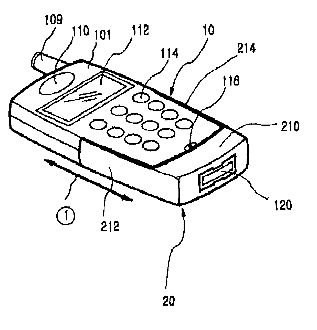
Figure 1 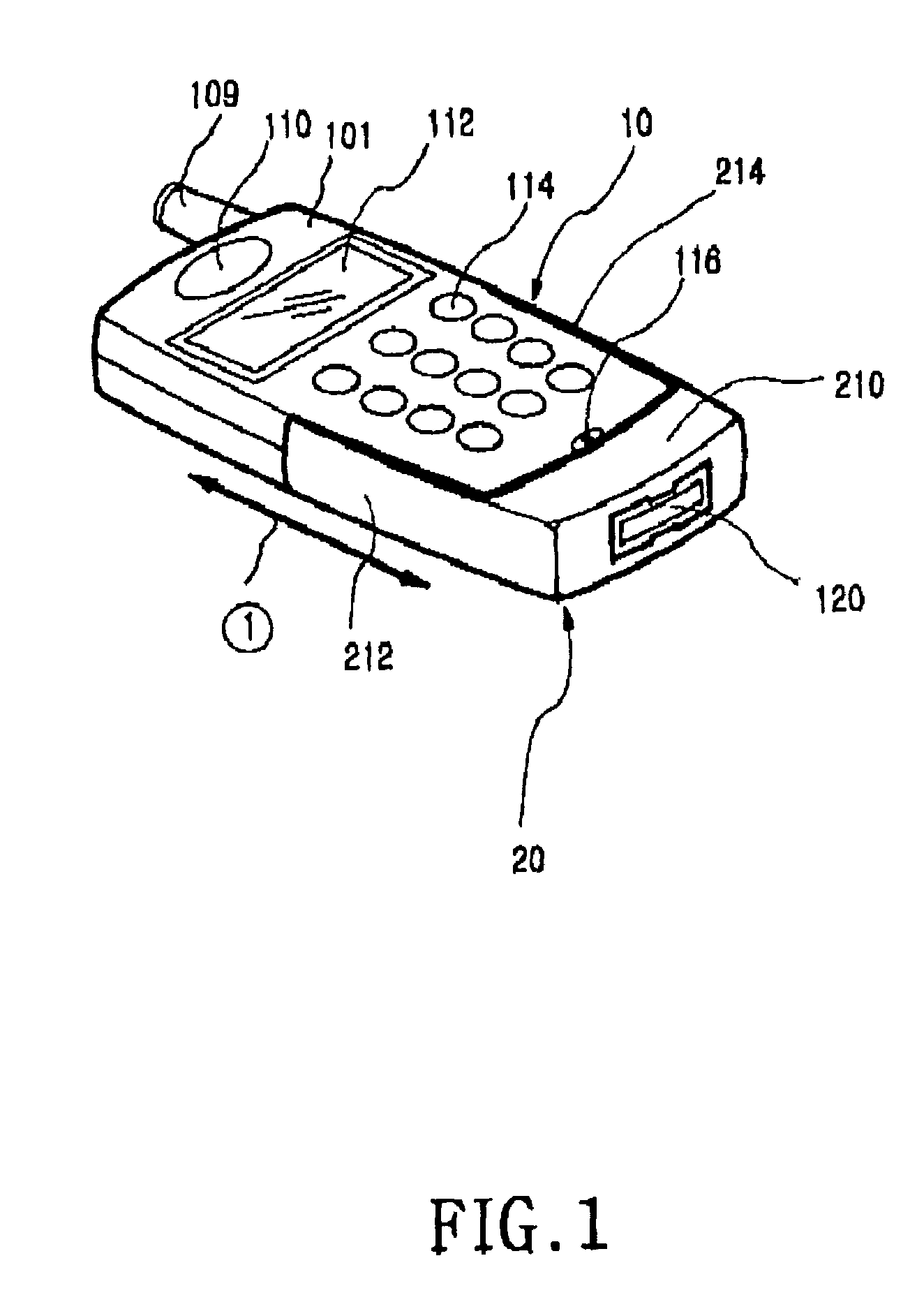
Figure 2 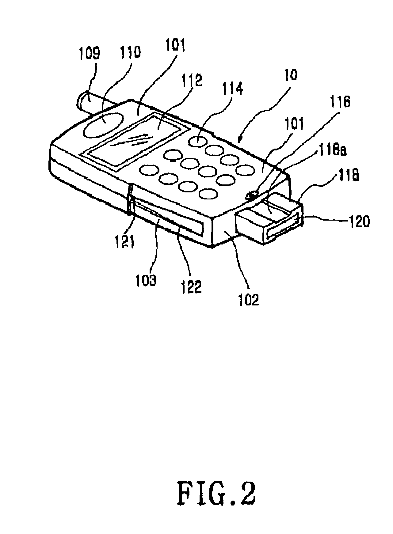
Figure 3
Abstract
Description
PRIORITY
[0001] This application claims priority to an application entitled “EXTERIOR-REPLACEABLE SUB-HOUSING AND FLIP-TYPE / BAR TYPE COMBINATION MOBILE PHONE THEREWITH”, filed in the Korean Industrial Property Office on Nov. 27, 2001 and assigned Ser. No. 2001-74391, the contents of which are hereby incorporated by reference.BACKGROUND OF THE INVENTION
[0002] 1. Field of the Invention
[0003] The present invention relates to a mobile telephone terminal, and more particularly to an interchangeable mobile telephone terminal provided with a replaceable sub-housing, thereby being used as a flip-type terminal and a bar-type terminal.
[0004] 2. Description of the Related Art
[0005] Usually, mobile telephone terminals, also referred to as portable units, communicate with a counterpart mobile terminal via wireless communication with a base station, such as voice communication, picture communication, data transmission, etc. That is, the mobile telephone terminals provide a wireless communication servic...
Examples
first embodiment
[0028]With reference to FIGS. 1 and 2, a mobile telephone terminal comprising a main housing 10 and a bar-type replaceable sub-housing 20 in accordance with the present invention is described in detail. The mobile telephone terminal as shown in FIGS. 1 and 2 comprises the main housing 10 and the bar-type replaceable sub-housing 20. The bar-type replaceable sub-housing 20 is attached to and detached from the main housing 10 in the longitudinal direction (in a direction of the arrow ①). Hereinafter, the replaceable sub-housing is referred to just as “the sub-housing”. If desired by a user, the sub-housing 20 may be detached from the main housing 10 and then replaced with a different type of sub-housing. That is, the sub-housing 20 detached from the main housing 10 may be replaced with another sub-housing with a different shape or color. Herein, the sub-housing 20 may be selected from a sub-housing with a flip (as shown in FIG. 8) or a sub-housing without the flip.
[0029]FIG. 1 shows a ...
second embodiment
[0039]As shown in FIG. 7, the main housing 40, which the sub-housing 30 of the present invention is attached to and detached from, includes an antenna unit 409, a speaker unit 410, a LCD 412, a key array including a plurality of keys 414, and a microphone unit 416 formed on a front surface 401 of the main housing 40. The main housing 40 comprises a front end 402, side ends 403, and a protrusion 418. The side ends 403 are formed on both side surfaces of the main housing 40. The protrusion 418 is extended from the front end 402 in the longitudinal direction. The protrusion 418 includes an interface connector 420 and a recess 418a formed on a designated area of one side surface of the protrusion 418. The recess 418a is extended along the longitudinal direction of the protrusion 418 and has a designated depth.
[0040]The protrusion 418 serves to firmly fix the coupling of the sub-housing 30 with the main housing 40 and to guide the sub-housing 30 onto the main housing 40 in the longitudin...