
Starter unit
a starter unit and multi-functional technology, applied in the direction of fluid couplings, gearings, couplings, etc., can solve the problems of increased slippage, low service life of the starter element, and the coupling device is then subject to increased wear, so as to achieve low design and control technology effort, low overall length, and easy integration into the drive system
Patent Information
- Authority / Receiving Office
- US · United States
- Patent Type
- Patents(United States)
- Current Assignee / Owner
- Publication Date
- 2007-01-09
- Estimated Expiration
- Not applicable · inactive patent
Smart Images
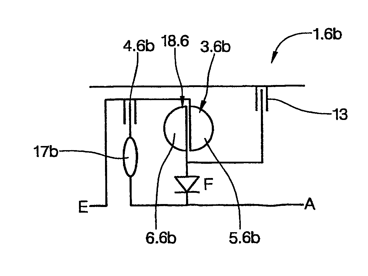
Figure 1 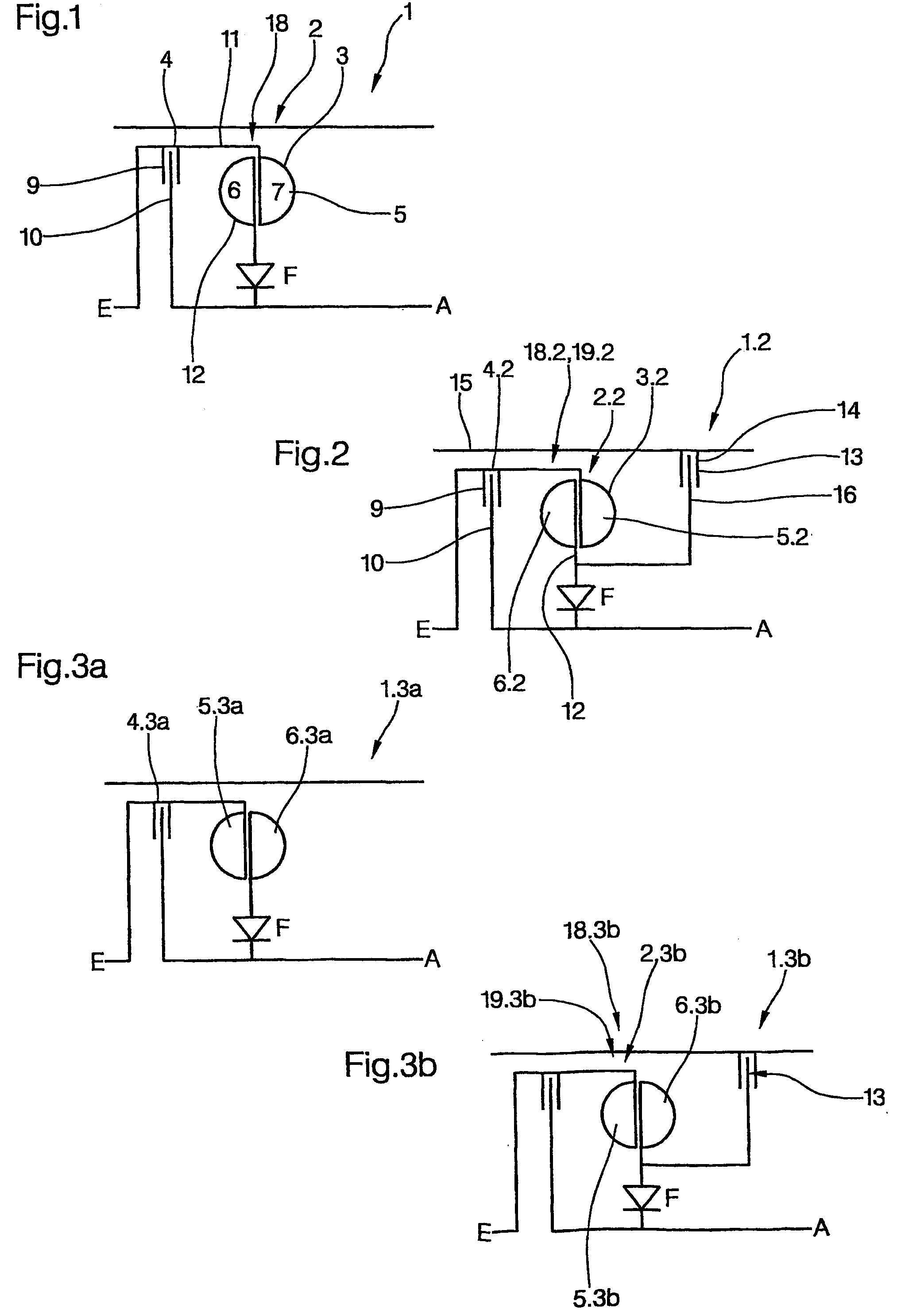
Figure 2 
Figure 3
Abstract
Description
BACKGROUND OF THE INVENTION
[0001] The invention relates to a multifunctional unit, particularly a starter unit for use in change-speed gearboxes, and particularly automatic and automated change-speed gearboxes, and it further relates to a change-speed gearbox, in particular an automated change-speed gearbox and to a vehicle with a change-speed gearbox.
[0002] Gearboxes for use in vehicles, in particular commercial vehicles, in the form of change-speed gearboxes or automated change-speed gearboxes are known in a large number of different embodiments. The starting process is usually realized using a coupling device in the form of a friction clutch or a hydrodynamic converter. However, use of a friction clutch as a starter element caused problems during operation, characterized by increased slip over a longer time period. This applies especially to the starting process. Due to the enormous thermal loading, the coupling device is then subjected to increased wear. In order to keep this wear...
Examples
Embodiment Construction
[0037]FIG. 1 is a schematic simplified representation of the basic construction of a starter unit 1 according to the invention, comprising a starter element 2. The starter unit 1 comprises a hydrodynamic component 18 in the form of a hydrodynamic coupling 3 and a bypass clutch 4. The hydrodynamic coupling 3 and the bypass clutch 4 are connected in parallel. The hydrodynamic coupling 3 comprises at least one primary wheel acting as a pump wheel 5 and a secondary wheel acting as a turbine wheel 6, which together form a toroidal working area 7. The bypass clutch 4 can be designed in one of many ways, but preferably in the form of a disk clutch, in particular a multiple disk clutch. This comprises a clutch input disk 9 and a clutch output disk 10, which can be brought into at least indirect active frictional contact with one another, i.e. either directly or via further disk-shaped intermediate elements, which form frictional pairs with one another. Furthermore, the starter unit 1 compri...