
Small hole diameter automatic measuring apparatus, small hole diameter measurement method, and shower plate manufacturing method
a technology of automatic measuring apparatus and small hole diameter, which is applied in the direction of fluid tightness measurement, instruments, other domestic articles, etc., can solve the problems of inability to accurately calculate the effective cross-sectional area a of the small hole, the flow meter itself is complicated, and the measurement of the diameter of the small hole cannot be performed quickly and efficiently, so as to achieve the effect of improving accuracy, reducing labor intensity and reducing labor intensity
Patent Information
- Authority / Receiving Office
- US · United States
- Patent Type
- Patents(United States)
- Current Assignee / Owner
- Publication Date
- 2007-05-22
Smart Images
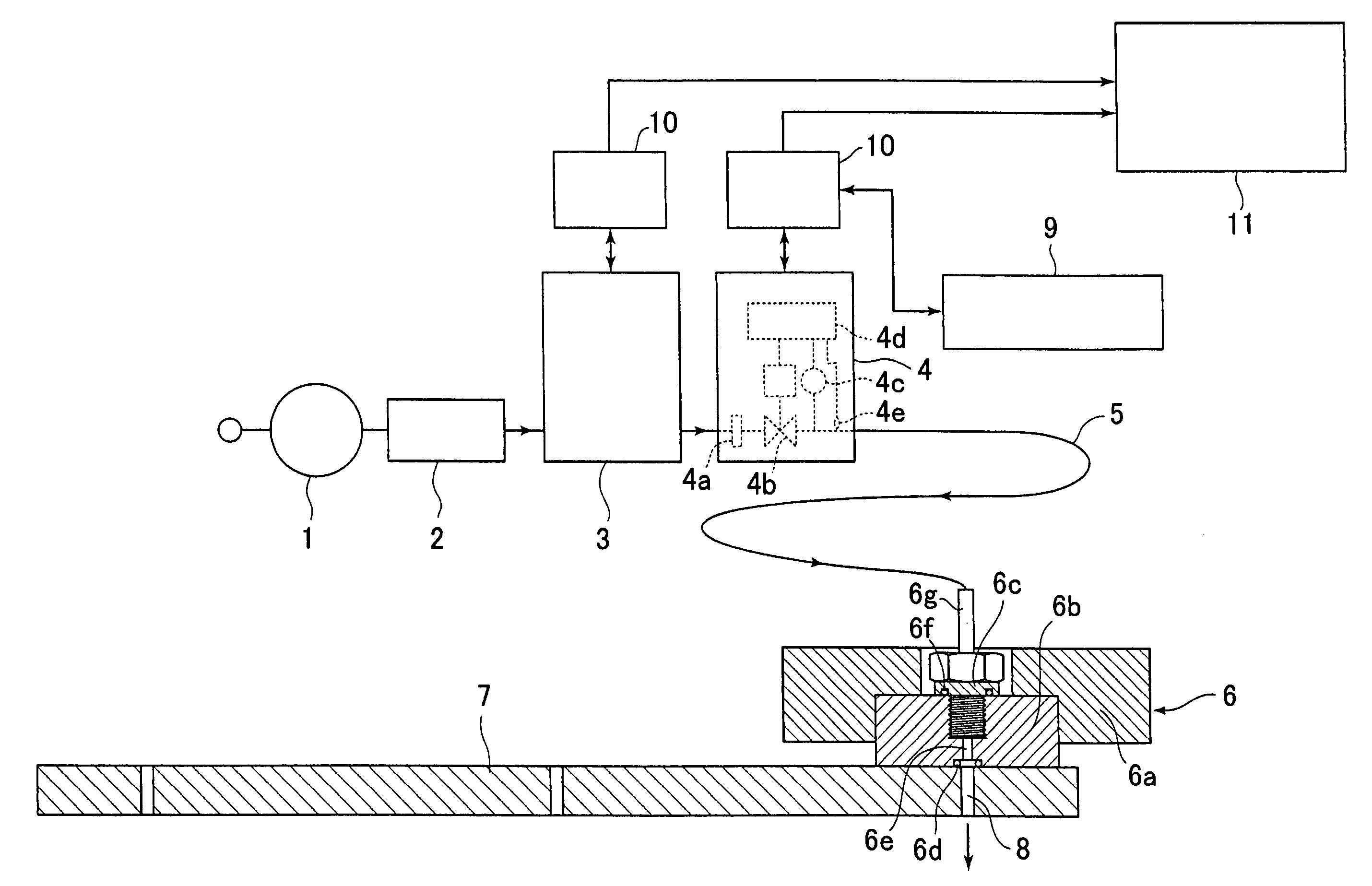
Figure 1 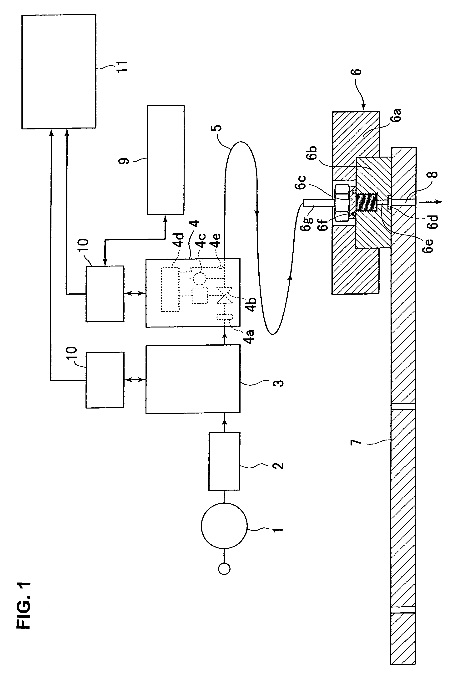
Figure 2 
Figure 3
Abstract
Description
BACKGROUND OF THE INVENTION
[0001] 1. Technical Field
[0002] The present invention relates to the measurement of the diameters of small holes formed in a substrate and more specifically relates to an improved system for the automatic measurement of the diameters of small holes formed in a plate such as the orifice diameter of a shower plate used for the disperse supply of a fluid (gas) in, for example, the vacuum chamber of a semiconductor manufacturing apparatus or the like. More concretely, the present invention relates to a small hole diameter measurement system for a plate in which the effective internal diameters of a plurality of small holes formed in a single plate can be automatically measured quickly and with high precision.
[0003] 2. Description of the Related Art
[0004] In semiconductor manufacturing equipment and liquid crystal displays, due to an increase in the size of the materials that are treated, it is necessary to maintain in-plane uniformity. Accordingly, for example, in...
Examples
Embodiment Construction
[0066]Below, basic experiments forming the foundation of the creation of the present invention will be described along with the results of these experiments, and respective embodiments of the present invention will be described, with reference to the figures.
[0067]FIG. 1 is an outline diagram of a test apparatus used to obtain basic data for the present invention; and in this figure, the reference numeral 1 indicates a pressure adjustment device, 2 indicates a filter, 3 indicates a thermal quantity type mass flow controller (rating: 500 SCCM), 4 indicates an automatic pressure control device, 5 indicates a connecting tube (PFA tube, 3.2 mm φ×3 m), 6 indicates a test probe, 7 indicates a plate, 8 indicates small holes in the plate, 9 indicates an operating control panel, 10 indicates a power supply device, and 11 indicates a pen recorder.
[0068]The above-described automatic pressure control device 4 is comprised of a filter 4a, a control valve 4b, a pressure detector 4c, a calculation...