
Throttle valve positioning device
Patent Information
- Authority / Receiving Office
- US · United States
- Current Assignee / Owner
- Publication Date
- 2007-07-03
- Estimated Expiration
- Not applicable · inactive patent
Smart Images
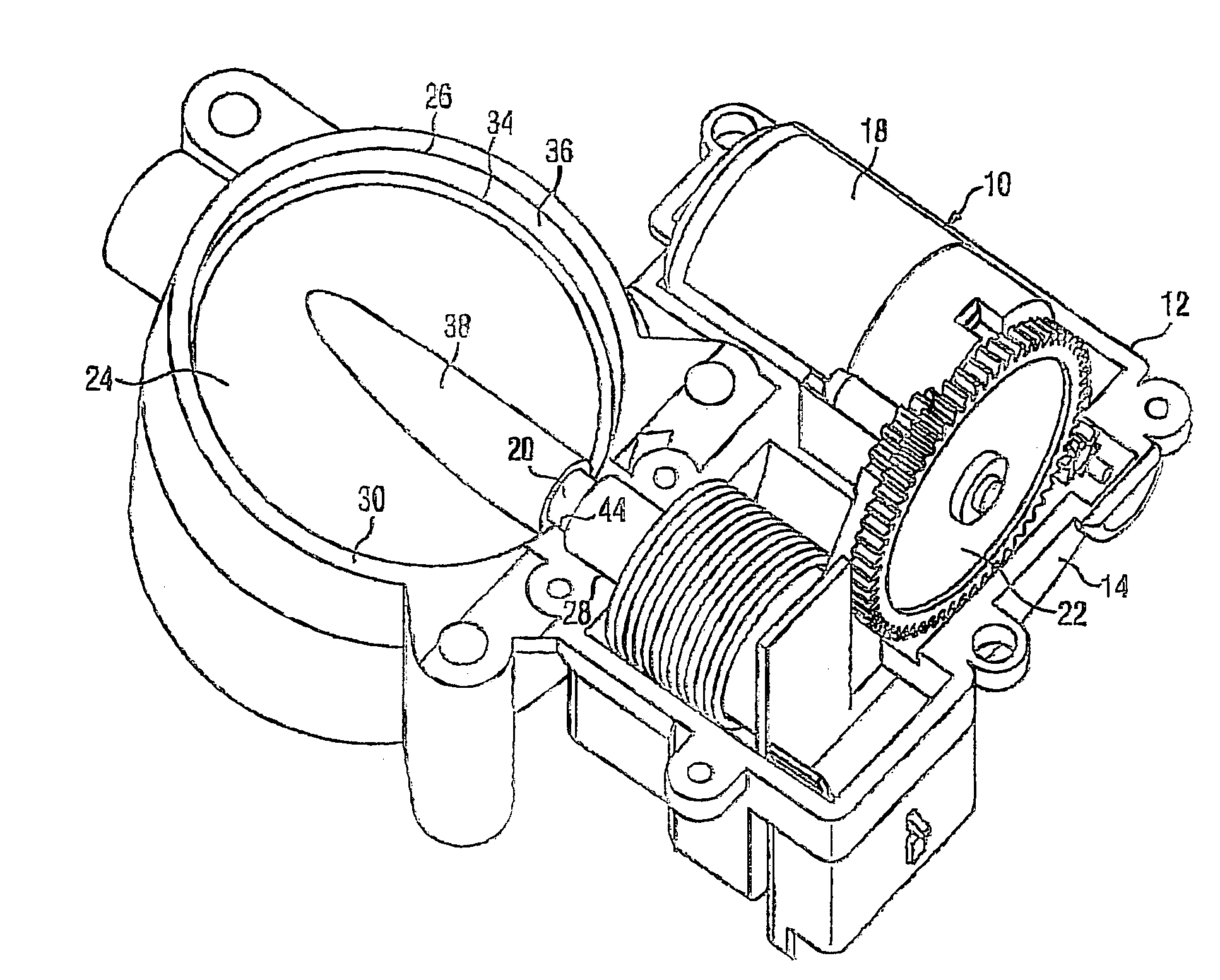
Figure 1 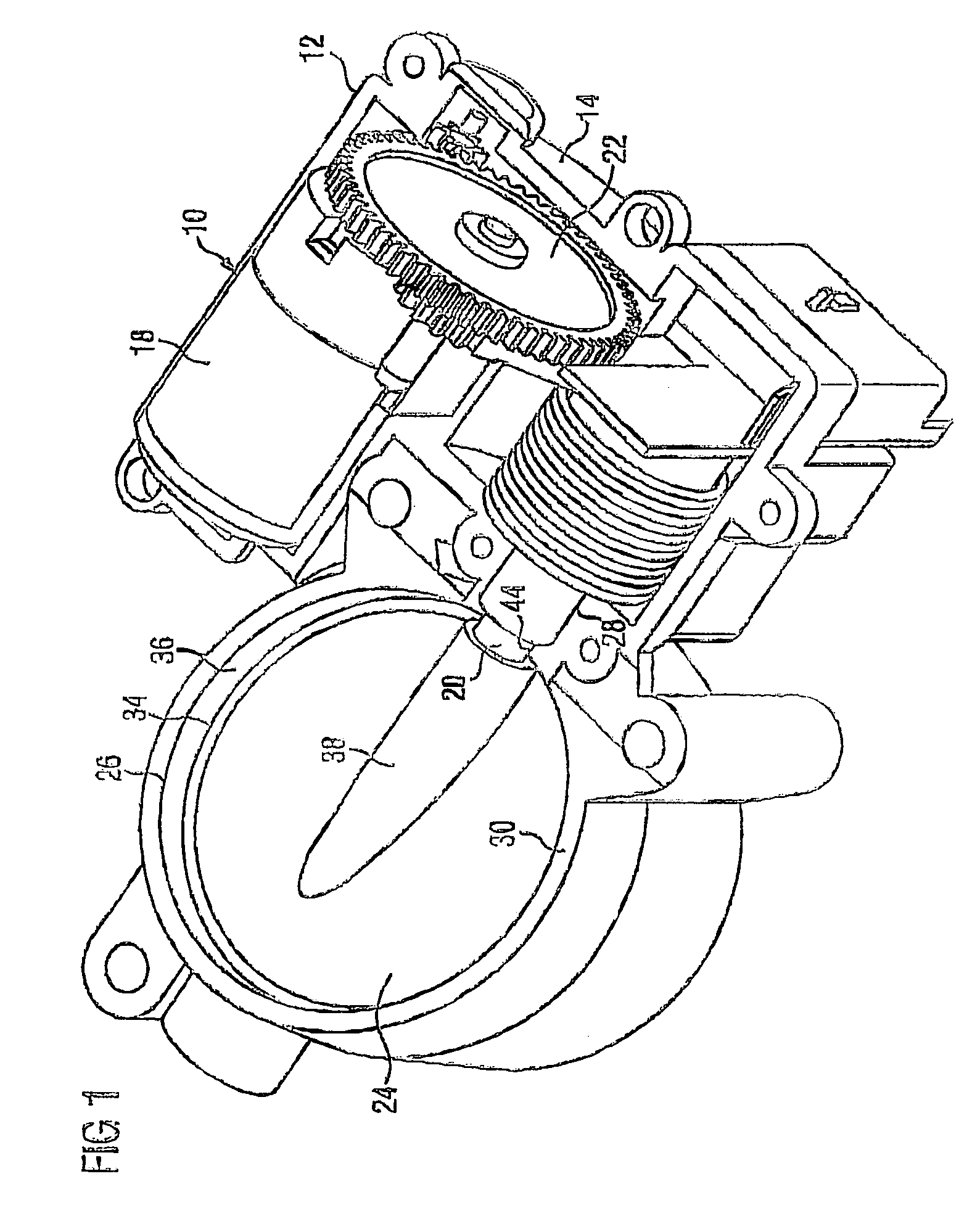
Figure 2 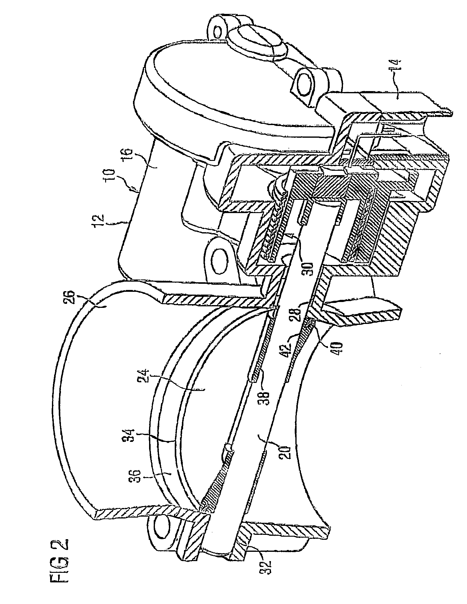
Figure 3
Abstract
Description
BACKGROUND OF THE INVENTION
[0001] The invention relates to a throttle valve positioning device having a housing which forms a bearing arrangement for a throttle valve shaft and comprises a throttle body in which a throttle valve is pivotable, said throttle valve sitting on the throttle valve shaft, which leads through the shaft passage into the throttle body, the housing being of split design, and the circumference of the throttle valve, at least on one side, lying next to the throttle valve shaft at a distance from a passage of the throttle valve shaft in the throttle body.
[0002] In the hitherto known arrangements of throttle valves in the throttle body which sit centrally on the throttle valve shaft or in a slot in the throttle valve shaft, leakage air usually cannot be prevented from flowing past in the region between throttle valve shaft, throttle valve and throttle housing and also via the shaft apertures in the bearings. The avoidance of leakage air is made more difficult in par...
Examples
Embodiment Construction
[0015]Shown in FIG. 1 is a throttle valve positioning device 10 which essentially comprises a housing 12 with a bottom housing half 14 and a top housing half 16, an actuator 18, a throttle valve shaft 20, which is coupled to the actuator 18 via gearing 22, and a throttle valve 24 which sits on the throttle valve shaft 20 and is pivotable in a throttle body 26 formed by the two housing halves 14, 16. In addition to a receptacle for the actuator 18 and the gearing 22, the housing also forms a bearing arrangement for the throttle valve shaft 20 at a first, drive-side bearing 28 in the parting line 30 between the two housing halves 14, 16 and at a second bearing 32 on the side opposite the drive in the throttle body 26. The second bearing 32 is at a distance from the parting line 30 between the housing halves and may also be designed as a closed bearing boss, whereas in FIG. 2 the bearing 32 is shown open outward.
[0016]The actuator 18 and the gearing 22 and also those regions of the two...