
Tip leakage flow directionality control
Patent Information
- Authority / Receiving Office
- US · United States
- Current Assignee / Owner
- Publication Date
- 2018-05-01
Smart Images
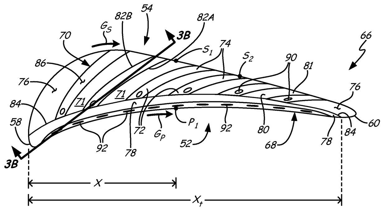
Figure 1 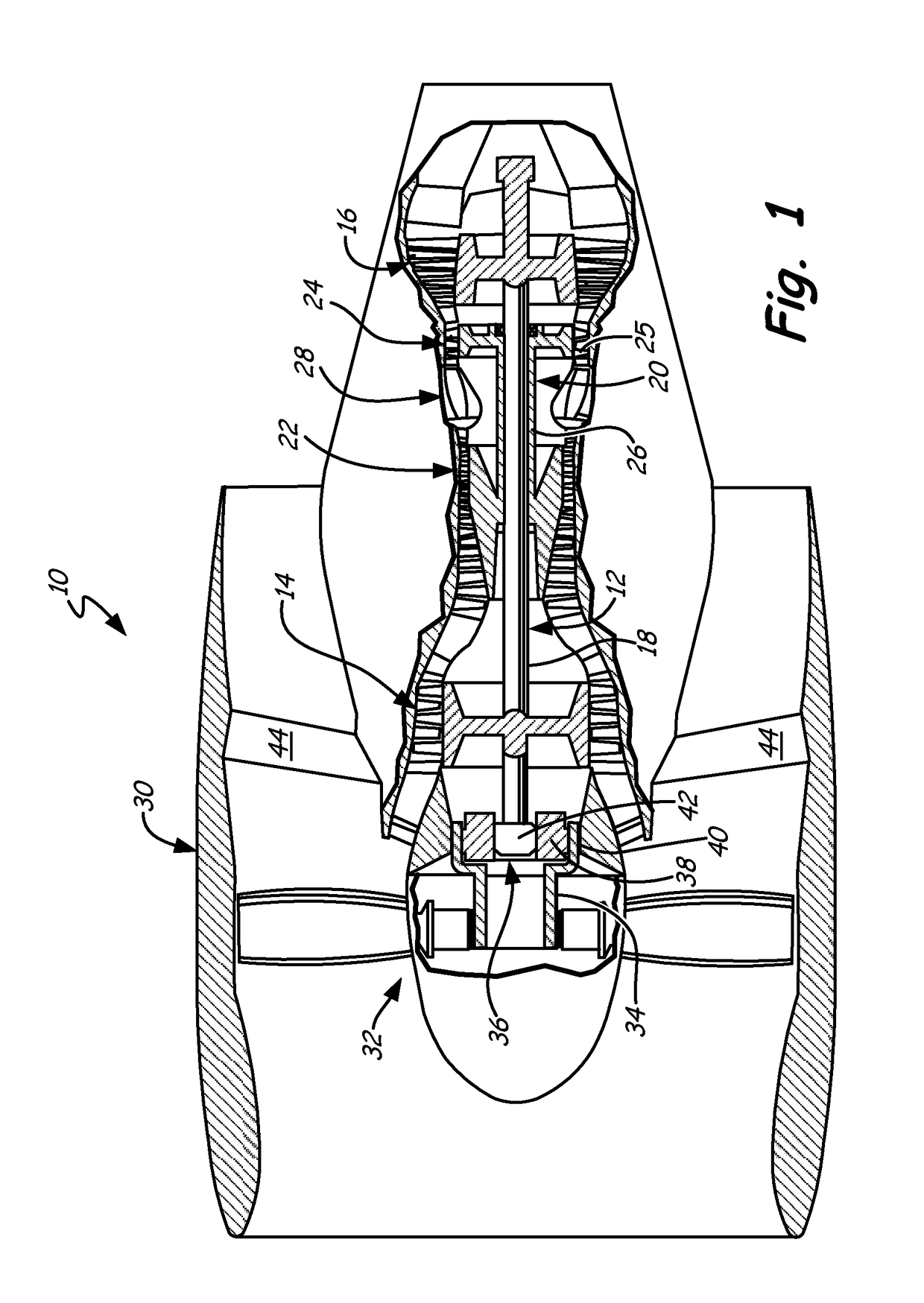
Figure 2 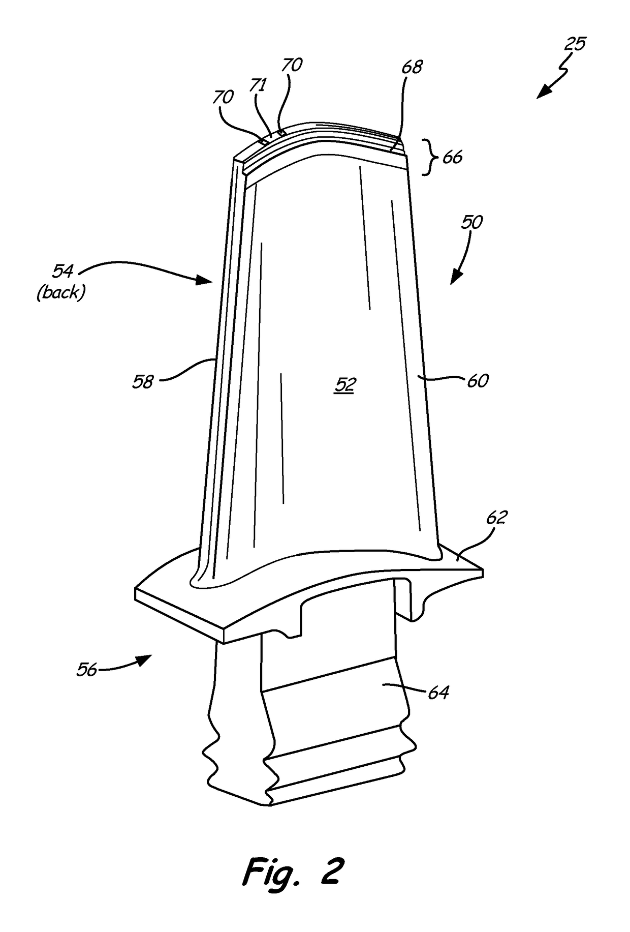
Figure 3
Abstract
Description
CROSS-REFERENCE TO RELATED APPLICATIONS
[0001] This application is a continuation-in-part of pending U.S. patent application Ser. No. 13 / 540,752, filed Jul. 3, 2012.BACKGROUND
[0002] The described subject matter relates generally to turbine engines and more specifically to cooling turbine blades.
[0003] Turbine engines provide efficient, reliable power for a wide range of applications in aviation, transportation and industrial power generation. Individual compressor and turbine section(s) may be subdivided into a number of stages, formed of alternating rows of rotor blade and stator vane airfoils. Due to various operational constraints, rotor blades and stator vanes are prone to leakage of compressed gases over their tips from a higher pressure surface to a lower pressure surface. Several attempts have been made to reduce these flows, but they cannot be completely eliminated due to clearance requirements over the airfoil tips which account for variations in both thermal and centrifugal gr...
Examples
Embodiment Construction
[0045]FIG. 1 is a cross-sectional view of gas turbine engine 10, including low spool 12, low pressure compressor (LPC) 14, low pressure turbine (LPT) 16, low pressure shaft 18, high spool 20, high pressure compressor (HPC) 22, high pressure turbine (HPT) 24, rotor blades 25, high pressure shaft 26, combustor 28, nacelle 30, propulsion fan 32, fan shaft 34, fan drive gear system 36, planetary gear 38, ring gear 40, sun gear 42, and fan exit guide vanes 44.
[0046]In the example two-spool, high bypass turbofan configuration, low spool 12 includes low pressure compressor (LPC) 14 driven by low pressure turbine (LPT) 16 via low pressure shaft 18. High spool 20 includes high pressure compressor (HPC) 22 driven by high pressure turbine (HPT) 24 via high pressure shaft 26. Low pressure shaft 18 and high pressure shaft 26 are mounted coaxially and rotate at different speeds. The power core also includes combustor 28 arranged in flow series between the compressor and turbine sections. HPT 24 a...