
Heat sink
a heat sink and heat sink technology, applied in the field of heat sinks, can solve the problems of increasing the heat dissipation efficiency of the conventional heat dissipation apparatus by increasing the length of the fins, and achieve the effect of effectively taking heat away from the fins, facilitating airflow, and efficient heat dissipation
Patent Information
- Authority / Receiving Office
- US · United States
- Patent Type
- Patents(United States)
- Current Assignee / Owner
- Publication Date
- 2007-10-30
- Estimated Expiration
- Not applicable · inactive patent
Smart Images
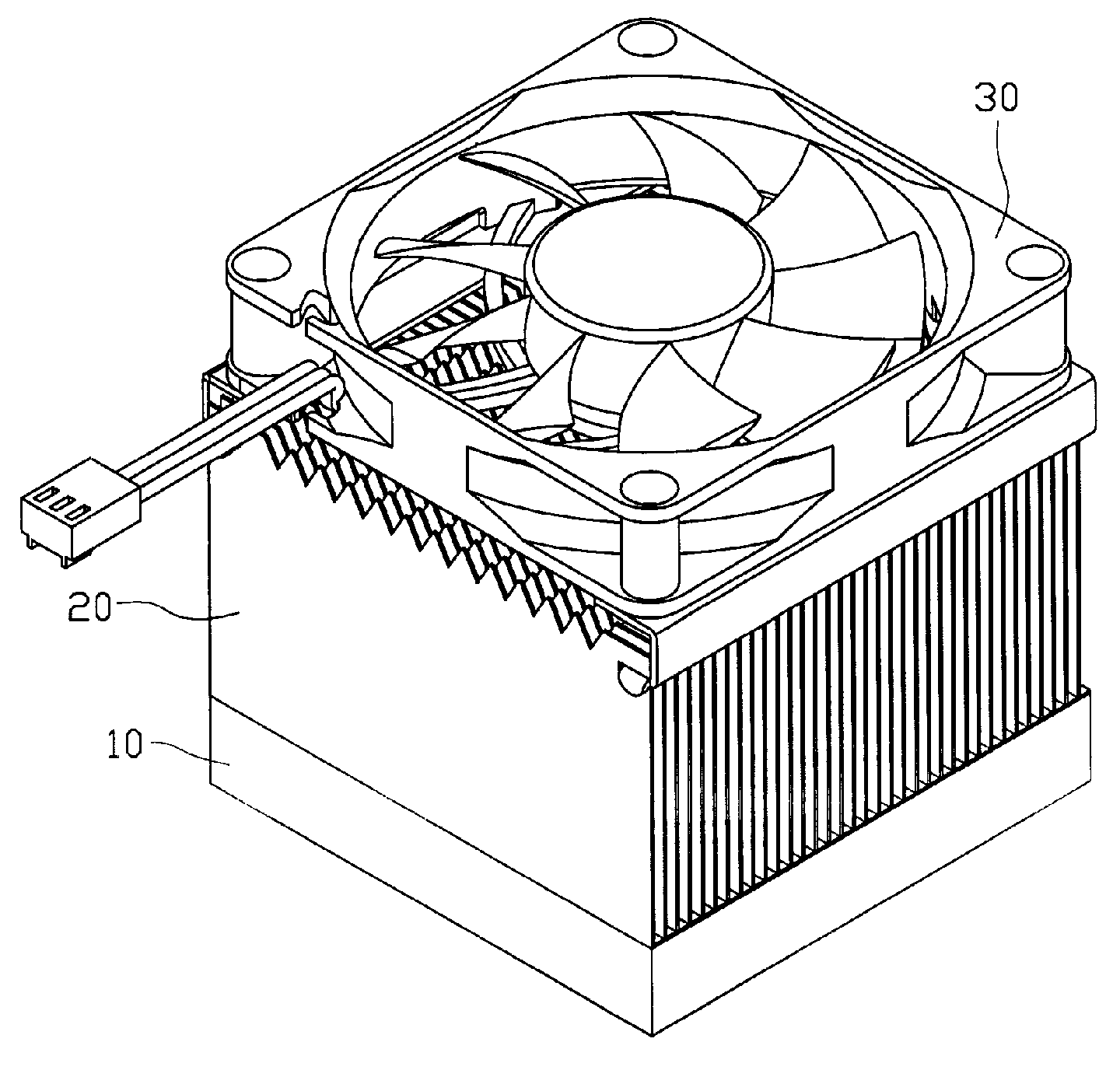
Figure 1 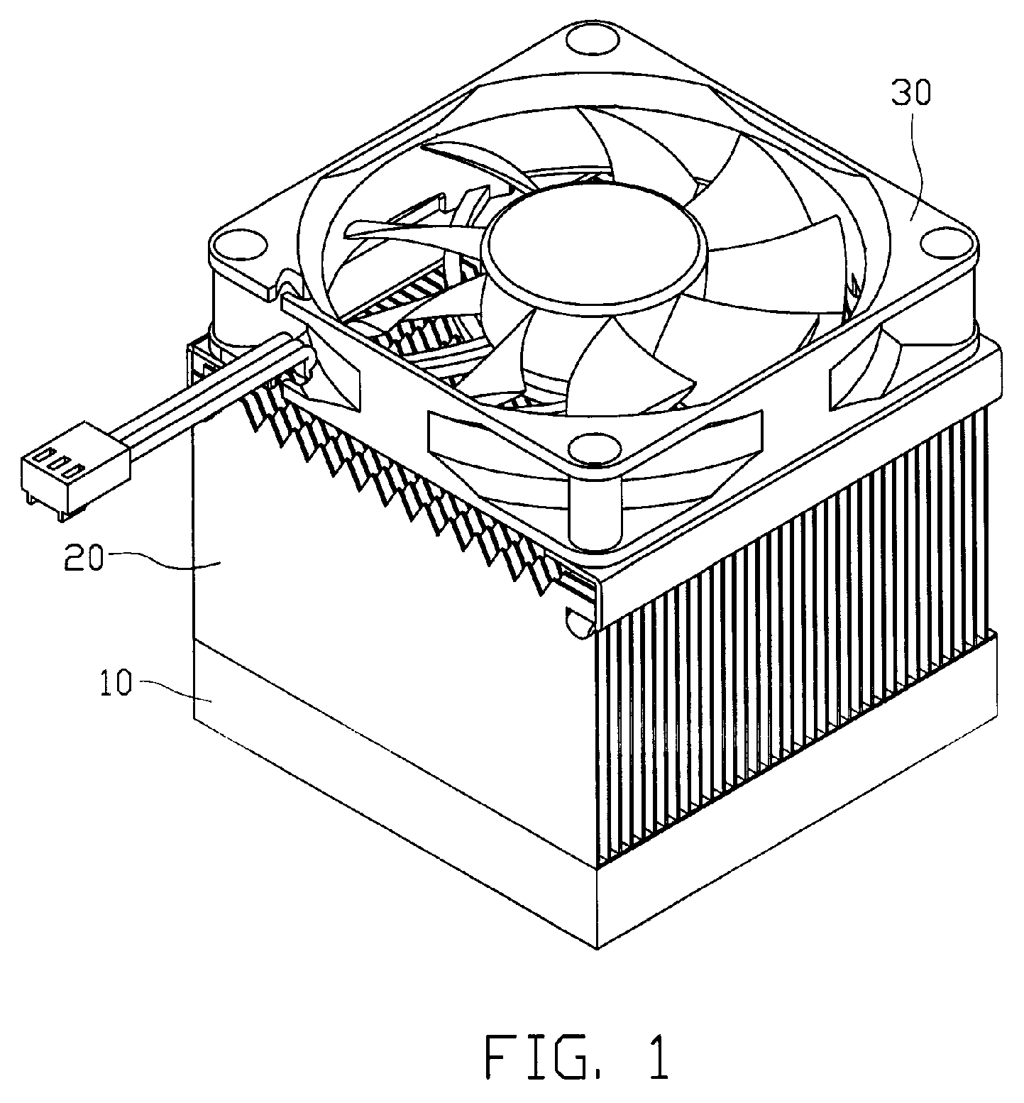
Figure 2 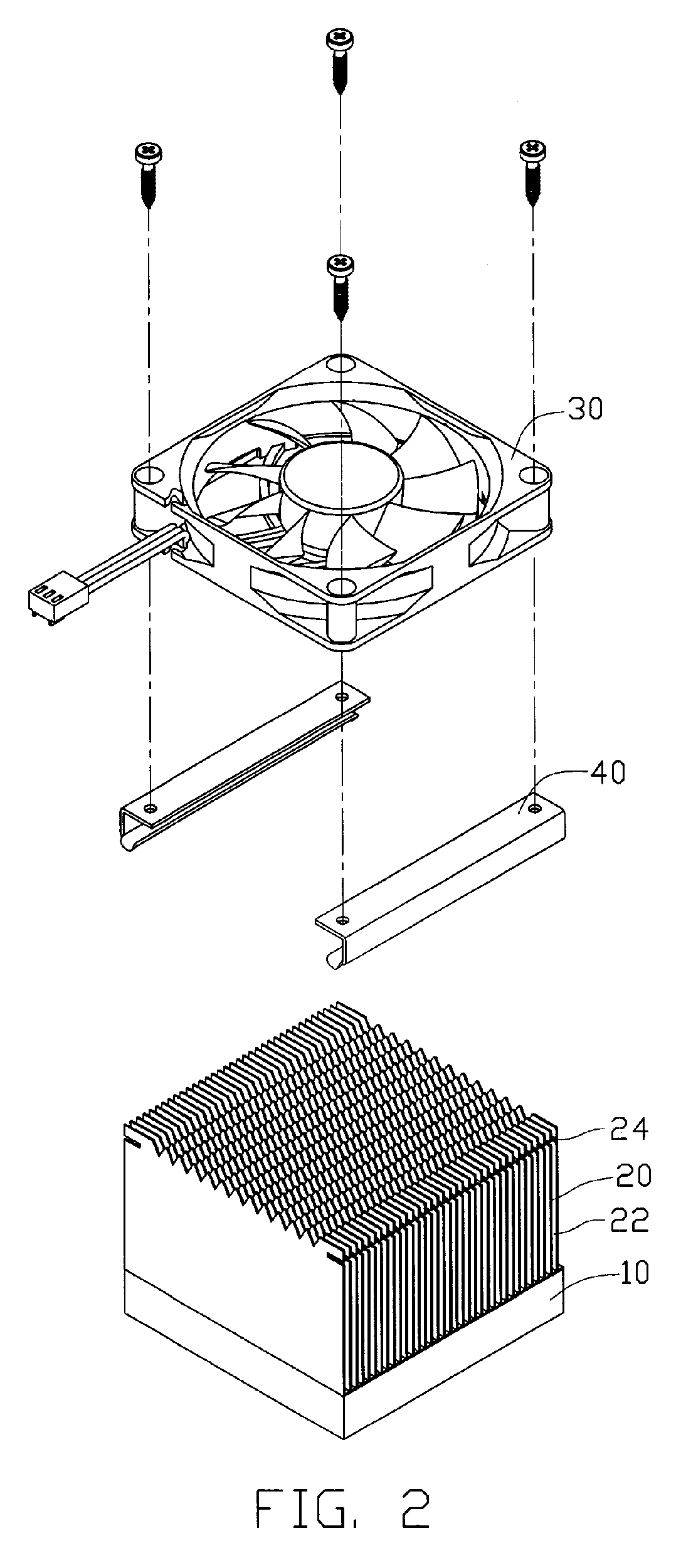
Figure 3
Abstract
Description
FIELD OF THE INVENTION
[0001] The present invention relates to a heat sink for removing heat from heat-generating electronic devices, and more particularly to a fin assembly of a heat sink with plate-like fins.DESCRIPTION OF RELATED ART
[0002] When a CPU of an electronic apparatus, for example, a computer is operated, heat must be quickly carried away from the CPU so that the operation of the CPU can be maintained normal. A conventional heat dissipating apparatus for this purpose generally includes a heat sink having a plurality of upright fins and adapted for mounting on a top of the CPU, and a fan adapted for mounting on the heat sink above the CPU. To provide an optimal heat transfer, the heat sink is designed to have, generally, a large surface area. The size of the surface area of a heat sink can generally determine the heat dissipating capacity of a heat sink. One way to increase the surface area of the heat sink is to increase the length of the fins; however, to increase the leng...
Examples
Embodiment Construction
[0014]Referring to FIGS. 1-2, a heat sink in accordance with a first preferred embodiment of the present invention comprises a base 10, a fin assembly 20 arranged on the base 10, and a fan 30 attachable to a top surface of the fin assembly 20 to blow cooling air downwards passing through the fin assembly 20.
[0015]The base 10 is made of a heat conductive material, such as copper or aluminum. The base 10 has a bottom surface for contacting a heat generating component (not shown) and an upper surface opposite to the bottom surface.
[0016]The fin assembly 20 comprises a plurality of individual fin plates 22 arranged side by side. Referring to FIG. 3, each fin plate 22 comprises a main body 222 and a flange 224 extends perpendicularly from a bottom edge of the main body 222. The flanges 224 are coplanar with each other. The fin assembly 20 can be mounted on the upper surface of the base 10 with the flanges 224 being soldered or glued thereto. The flanges 224 are formed to also facilitate ...