
DNA analyzing apparatus, DNA sensor, and analyzing method
a technology which is applied in the field of dna analyzing apparatus and dna sensor, can solve the problem that the sample dna fragment cannot be hybridized with the corresponding probe dna fragment, and achieve the effect of rapid hybridization and reduced speed
Patent Information
- Authority / Receiving Office
- US · United States
- Patent Type
- Patents(United States)
- Current Assignee / Owner
- Publication Date
- 2010-11-02
- Estimated Expiration
- Not applicable · inactive patent
Smart Images
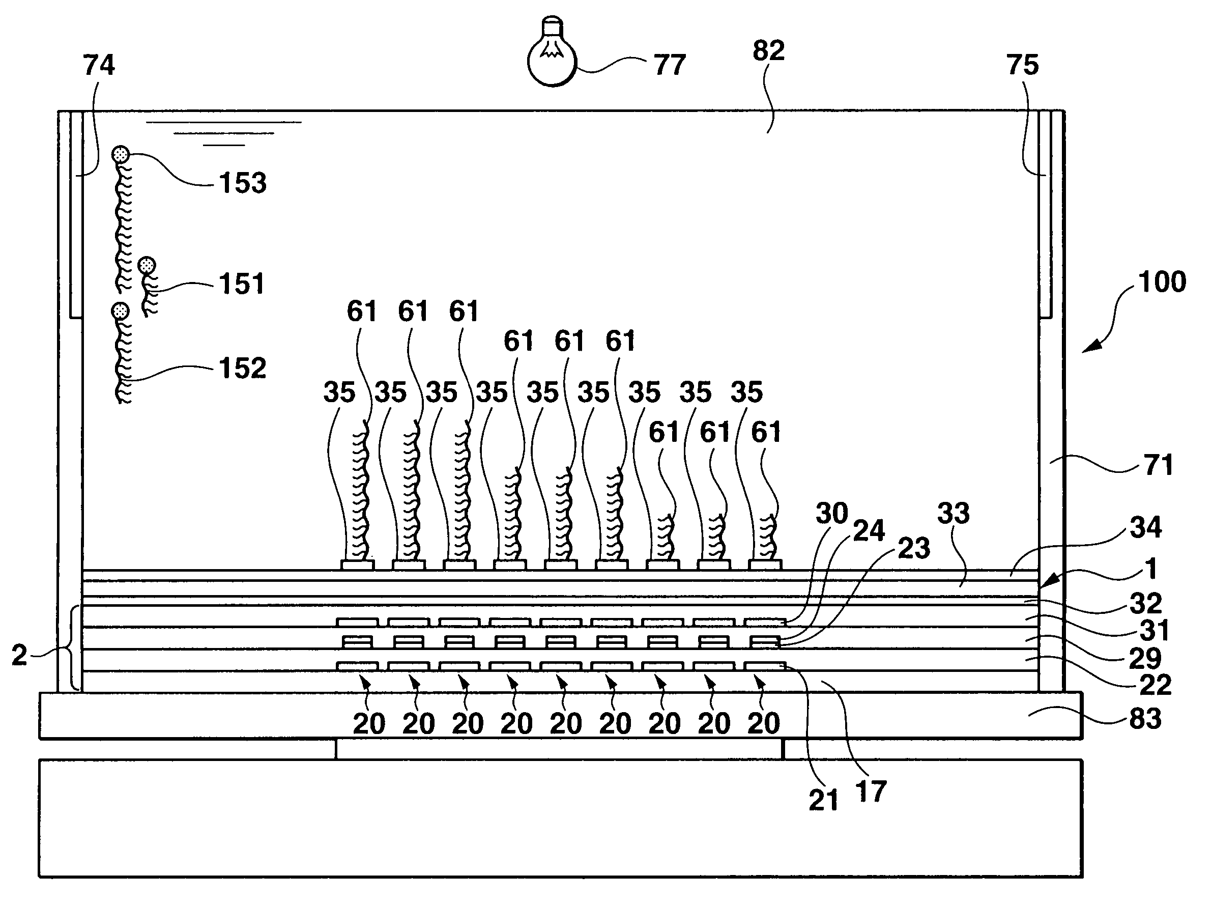
Figure 1 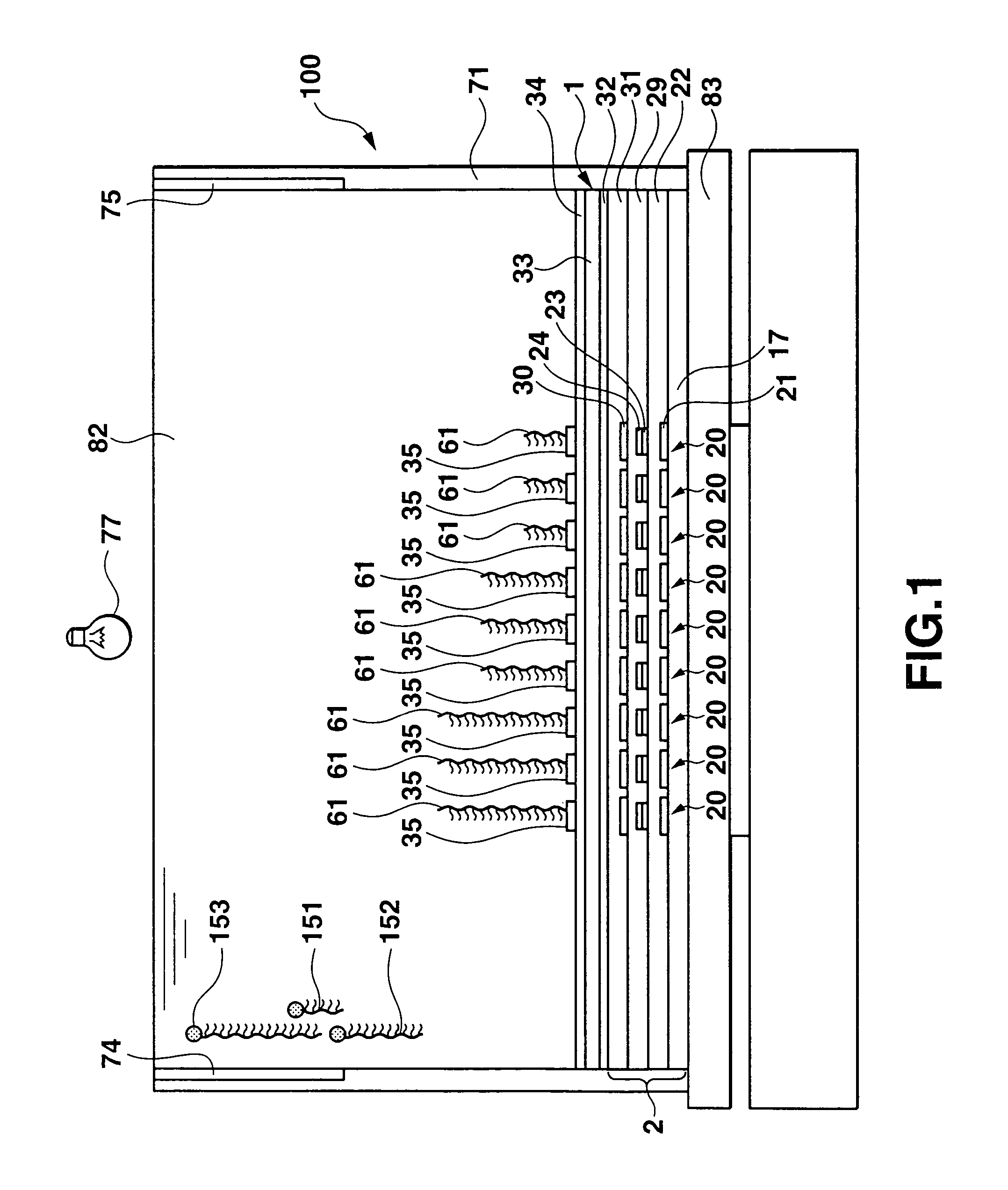
Figure 2 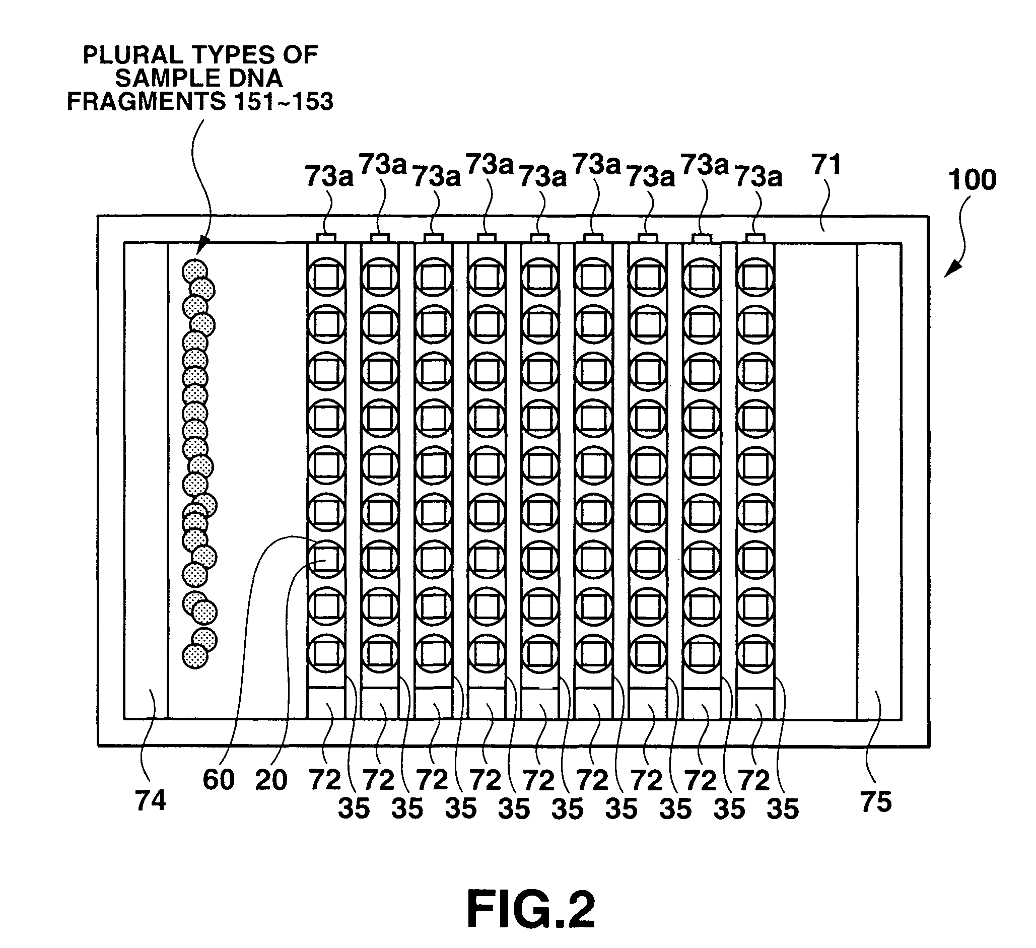
Figure 3
Abstract
Description
CROSS-REFERENCE TO RELATED APPLICATIONS
[0001] This is a Continuation Application of PCT Application No. PCT / JP2004 / 002772, filed Mar. 4, 2004, which was published under PCT Article 21(2) in English.
[0002] This application is based upon and claims the benefit of priority from prior Japanese Patent Applications No. 2003-063712, filed Mar. 10, 2003; and No. 2003-063755, filed Mar. 10, 2003, the entire contents of both of which are incorporated herein by reference.BACKGROUND OF THE INVENTION
[0003] 1. Field of the Invention
[0004] The present invention relates to a DNA analyzing apparatus, a DNA sensor, and an analyzing method which are used to analyze DNAs having different numbers of bases.
[0005] 2. Description of the Related Art
[0006] In recent years, information on biological genes has been utilized in various fields such as medical care and agriculture. It is essential to understand the structures of DNAs in utilizing genetic information. A DNA has two spirally twisted polynucleotide chains...
Examples
Embodiment Construction
[0111]A specific embodiment of the present invention will be described below with reference to the drawings. However, the scope of the present invention is not limited to the illustrated examples.
[0112]FIG. 1 is an exploded front view showing a DNA identifying apparatus 100 that analyzes DNAs. FIG. 2 is a top plan view of the DNA identifying apparatus 100.
[0113]The DNA identifying apparatus 100 comprises a bath 71, an ultraviolet irradiator 77 located above the bath 71, first and second electrodes 74, 75 arranged on the upper parts of inside of the bath 71 and horizontally opposite each other in a width direction of the bath 71, and a DNA sensor 1 that can be installed at and removed from the bottom of the bath 71.
[0114]The DNA sensor 1 will be described with reference to FIGS. 3, 4A, and 4B. FIG. 3 is a plan view of the DNA sensor 1. FIG. 4A is a plan view showing one pixel of the DNA sensor 1. FIG. 4B is an exploded sectional view taken along line (IVB)-(IVB) in FIG. 4A.
[0115]The ...