
Grooving pattern for grooved fluid bearing
Patent Information
- Authority / Receiving Office
- US · United States
- Current Assignee / Owner
- Publication Date
- 2006-08-15
- Estimated Expiration
- Not applicable · inactive patent
Smart Images
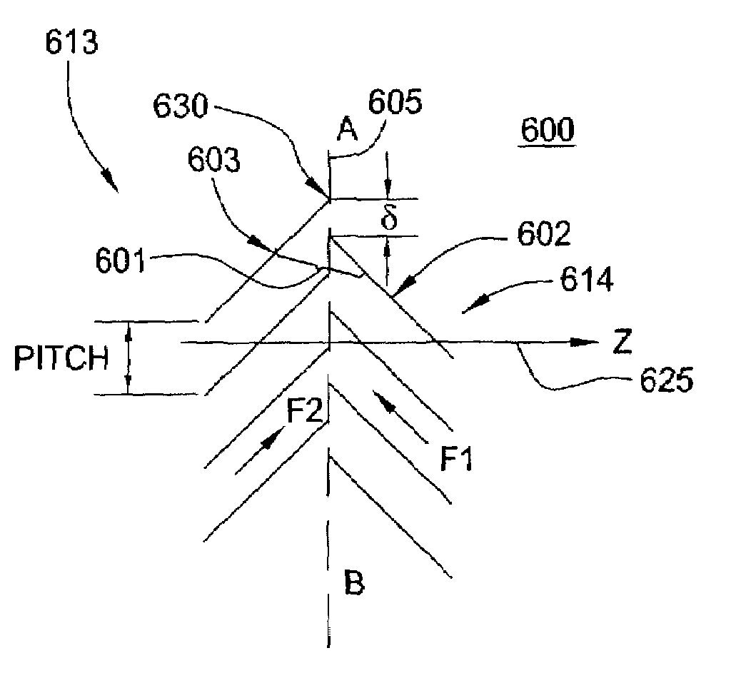
Figure 1 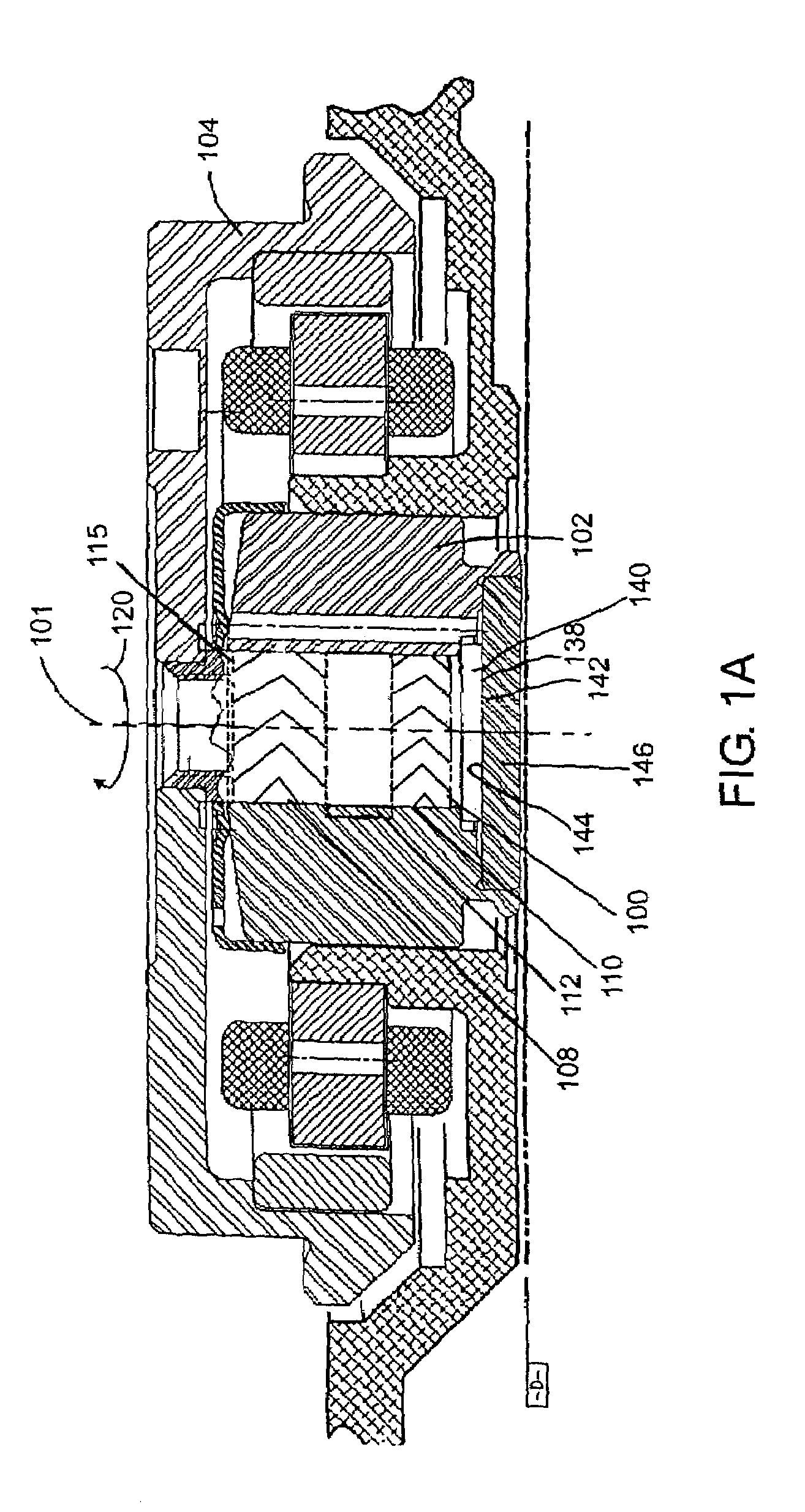
Figure 2 
Figure 3
Abstract
Description
FIELD OF THE INVENTION
[0001] This application claims priority to U.S. Provisional Patent Application Ser. No. 60 / 441,675, filed Jan. 21, 2003 by Mohamed Rahman, Gunter Heine, Hans Leuthold and Anthony Aiello, entitled Grooves to Enhance the Critical Bearing Performances, which is herein incorporated by reference.FIELD OF THE INVENTION
[0002] The present invention generally relates to the field of fluid dynamic bearings, and more specifically relates to grooving patterns used in fluid dynamic bearings.BACKGROUND OF THE INVENTION
[0003] Disk drive memory systems have been used in computers for many years for the storage of digital information. Information is recorded on concentric tracks of a magnetic disk medium, the actual information being stored in the form of magnetic transitions within the medium. The disks themselves are rotatably mounted on a spindle. Information is accessed by a read / write transducer located on a pivoting arm that moves radially over the surface of the rotating di...
Examples
Embodiment Construction
[0034]FIGS. 1A and 1B show disc drive spindle motors in which the groove designs of the present invention are useful. However, the grooves to be described below are useful in most, if not all fluid dynamic bearings; they are described herein incorporated in a disc drive spindle motor merely for purposes of illustration.
[0035]FIG. 1A is a vertical sectional view of a shaft 100 rotating within a sleeve and supporting a hub 104 for rotation with the shaft. The hub 104 supports one or more discs for rotation within the disc drive. To provide a stable support between the sleeve 102 and shaft 100, fluid dynamic journal bearings 108, 110 are typically provided in the gap 112 between the inner surface of sleeve 102 and the outer surface of shaft 100. An exemplary prior art bearing pattern, similar to the bearing pattern shown in FIG. 2 is shown in the two groove bearing regions 108 and 110 which support the shaft 100 for rotation. The arrow 120 seen at the top of FIG. 1A indicates that the ...