

Two-stroke internal combustion engine
a two-stroke, internal combustion engine technology, applied in combustion engines, cylinders, pipes, etc., can solve the problems of reducing affecting the combustion efficiency of the engine, and the cylinders are difficult to mold, so as to improve the combustion efficiency, and reduce the passage sectional area
Patent Information
- Authority / Receiving Office
- US · United States
- Patent Type
- Patents(United States)
- Current Assignee / Owner
- Publication Date
- 2013-01-15
Smart Images
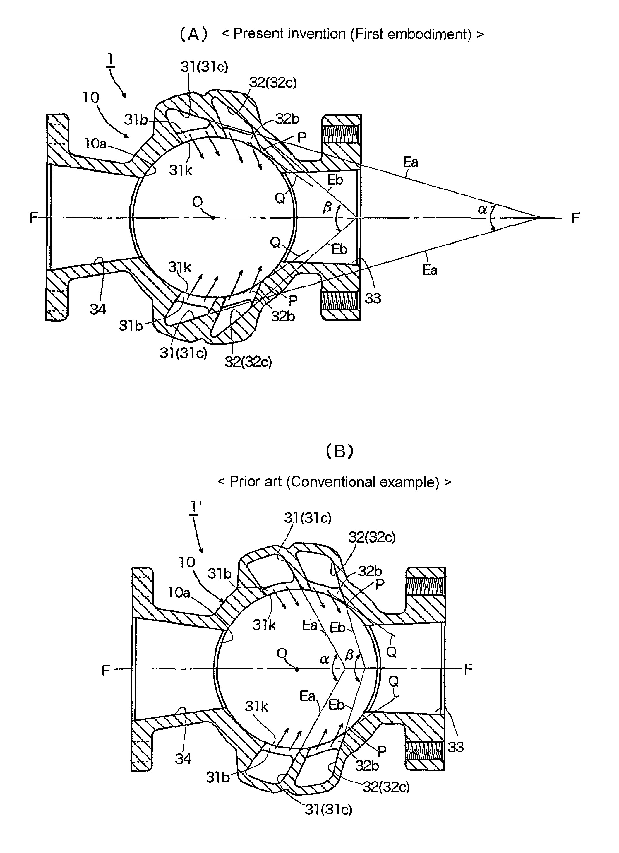
Figure 1 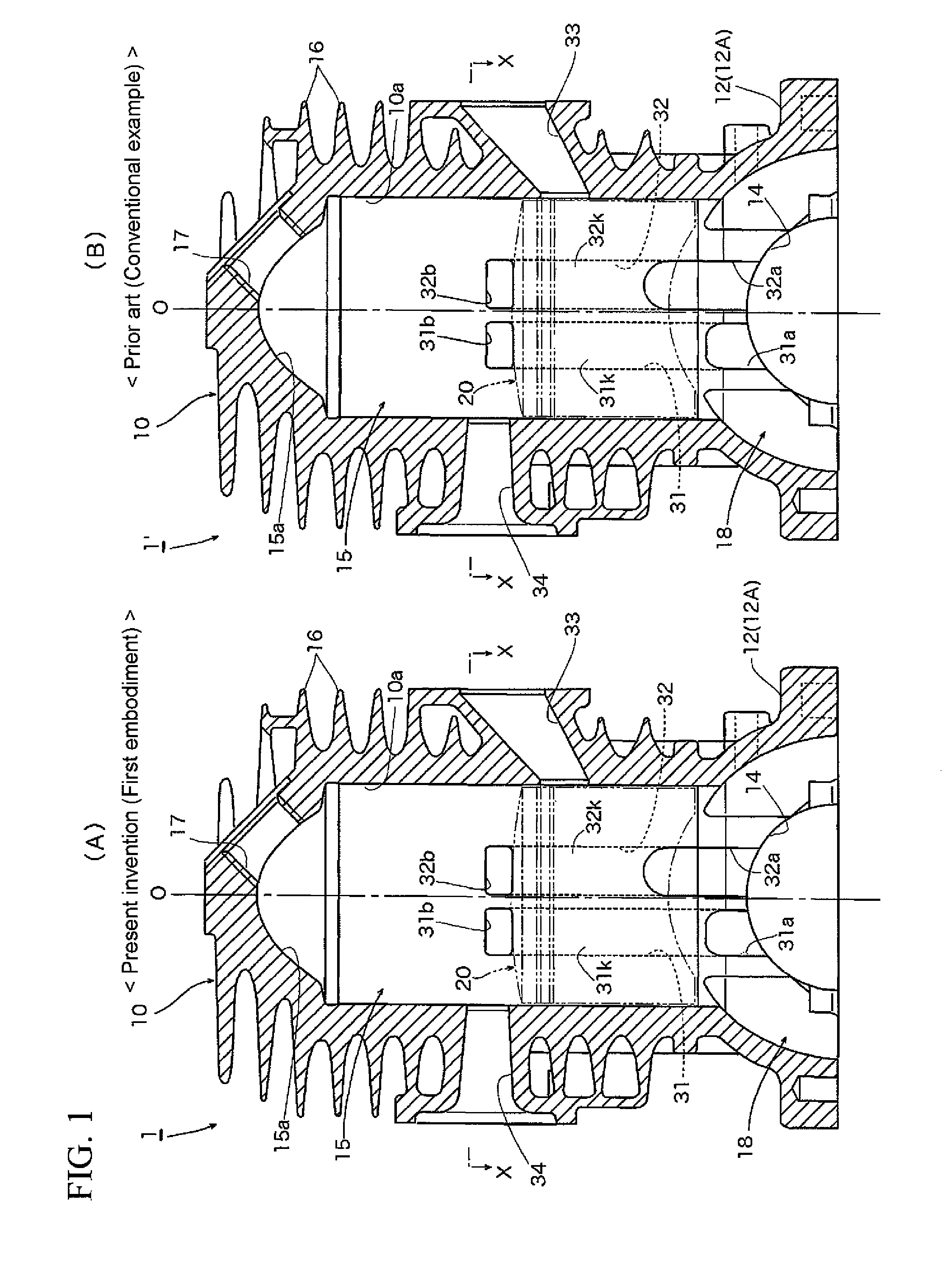
Figure 2 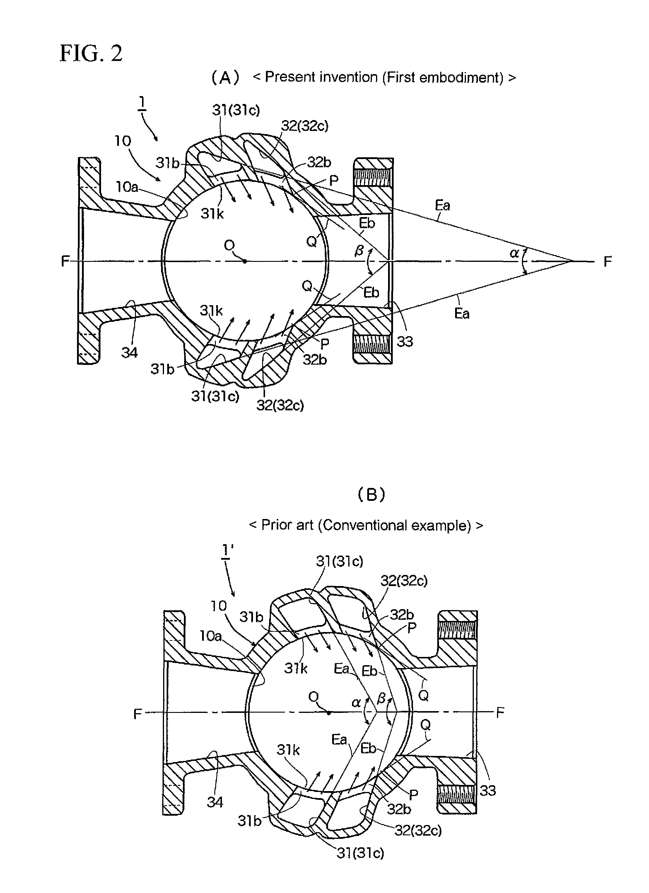
Figure 3
Abstract
Description
[0001] 1. Field of the Invention
[0002] The present invention relates to two-stroke internal combustion engines comprising one pair or a plurality of pairs of scavenging passages that adopt a reverse scavenging system, and more specifically to two-stroke internal combustion engines that are capable of suppressing the short-circuiting of fresh charge (unburnt air-fuel mixture), while at the same time also being capable of improving scavenging efficiency, combustion efficiency, and the like.
[0003] 2. Background Art
[0004] Ordinarily, in standard two-stroke gasoline engines conventionally used in portable powered work machines, such as lawn mowers, chainsaws, etc., a spark plug is disposed at a head portion of a cylinder. An intake port, a scavenging port, and an exhaust port that are opened / closed by a piston are formed in a barrel portion of the cylinder. There are no independent strokes dedicated to intake and exhaust alone. And one cycle of the engine is completed w...
Examples
Embodiment Construction
[0050]Embodiments of the present invention (first and second embodiments) are described below with reference to the drawings.
[0051]FIG. 1(A) is a vertical sectional view of an embodiment (first embodiment) of a reverse scavenged two-stroke internal combustion engine according to the present invention, and FIG. 1(B) is a vertical sectional view of a conventional example of a reverse scavenged two-stroke internal combustion engine. FIG. 2(A) is a sectional view taken along and as viewed in the direction of arrows X-X in FIG. 1(A), and FIG. 2(B) is a sectional view taken along and as viewed in the direction of arrows X-X in FIG. 1(B). FIG. 3(A) is a base view of the main portion of the engine shown in FIG. 1(A), and FIG. 3(B) is a base view of the main portion of the engine shown in FIG. 1(B). Line O-O in FIGS. 1(A) and 1(B) illustrates the axis of cylinder 10, defined through the center O of cylinder 10 illustrated in FIGS. 2(A)-2(B) and 3(A)-3(B). With respect to the engines of the f...