

Display apparatus, quantity-of-light adjusting method for display apparatus and electronic equipment
a technology of display apparatus and quantity of light, which is applied in the direction of instruments, static indicating devices, electroluminescent light sources, etc., to achieve the effects of reducing the luminance of light sources, constant chromaticity, and extending the range of luminance control in the display apparatus in the electronic equipmen
Patent Information
- Authority / Receiving Office
- US · United States
- Patent Type
- Patents(United States)
- Current Assignee / Owner
- Publication Date
- 2014-09-09
Smart Images
Figure 1 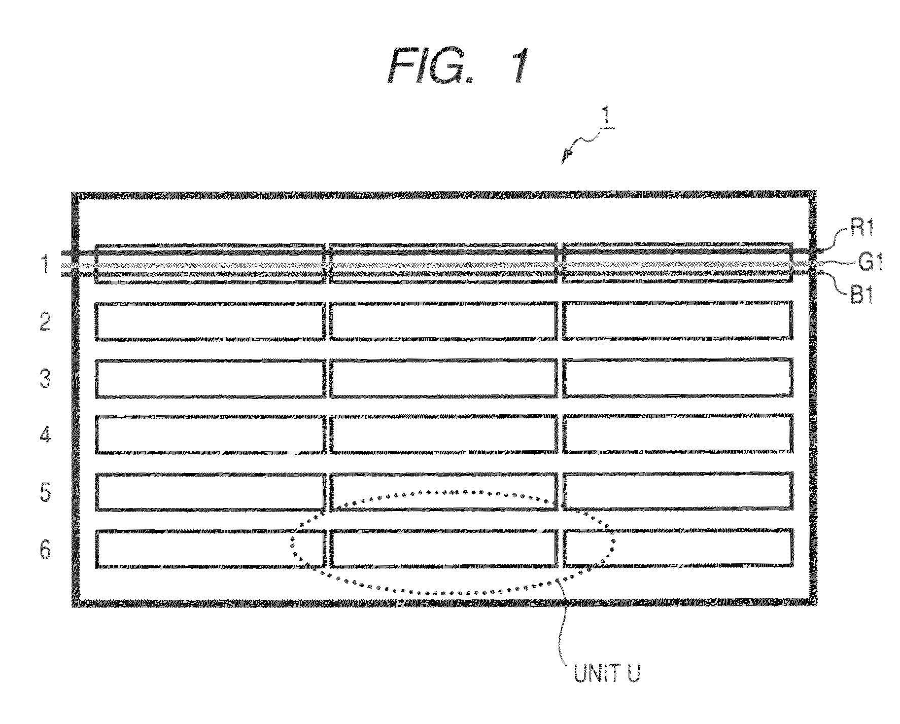
Figure 2 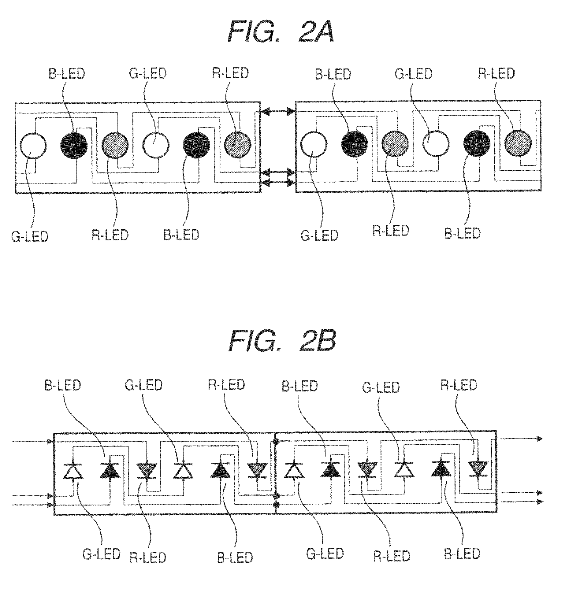
Figure 3
Abstract
Description
CROSS REFERENCES TO RELATED APPLICATIONS
[0001] The present application claims priority from Japanese Patent Application JP No. 2007-268576 filed in the Japanese Patent Office on Oct. 16, 2007, the entire content of which is incorporated herein by reference.BACKGROUND OF THE INVENTION
[0002] 1. Field of the Invention
[0003] The present invention relates to a display apparatus that displays an image by irradiating light from a light source to display means, a quantity-of-light adjusting method for a display apparatus and electronic equipment.
[0004] 2. Description of the Related Art
[0005] Liquid crystal displays including a liquid crystal television may use an LED (or light emitting diode) device as a back light thereof for one advantage that the range of the luminance control is wider than that of a CCFL (Cold Cathode Fluorescent Lamp) (refer to JP-A-2005-310997 (Patent Document 1), for example).
[0006] The CCFL may also control the luminance and mainly includes two methods of voltage light co...
Examples
Embodiment Construction
[0053]With reference to drawings, embodiments of the invention will be described.
[Layout in LED Back Light]
[0054]FIG. 1 is a schematic plan view illustrating the layout in an LED back light. An LED back light is placed at the back of display means (such as a liquid crystal panel) in a display apparatus 1 and supplies light to the display means. In the LED back light, one unit U has multiple R, G and B LEDs, and the units U are placed horizontally and vertically. As the area of the display means such as a liquid crystal panel increases, the number of units U disposed vertically and horizontally increases. However, one unit U may be provided for display means in a smaller area.
[Configuration of Unit]
[0055]FIGS. 2A and 2B are schematic diagrams illustrating a configuration of an LED unit employed in an LED back light, and FIG. 2A is a layout diagram, and FIG. 2B is a circuit diagram. In one unit, R (red), G (green) and B (Blue) LEDs (or R-LED, G-LED and B-LED) are laid out in a predete...