
Imaging apparatus
a technology of imaging apparatus and viewfinder, which is applied in the field of imaging apparatus, can solve the problems of increasing man-hours and costs, preventing the observation of images, and adhering to the interior of the viewfinder,
Patent Information
- Authority / Receiving Office
- US · United States
- Patent Type
- Patents(United States)
- Current Assignee / Owner
- Publication Date
- 2015-03-31
- Estimated Expiration
- Not applicable · inactive patent
Smart Images
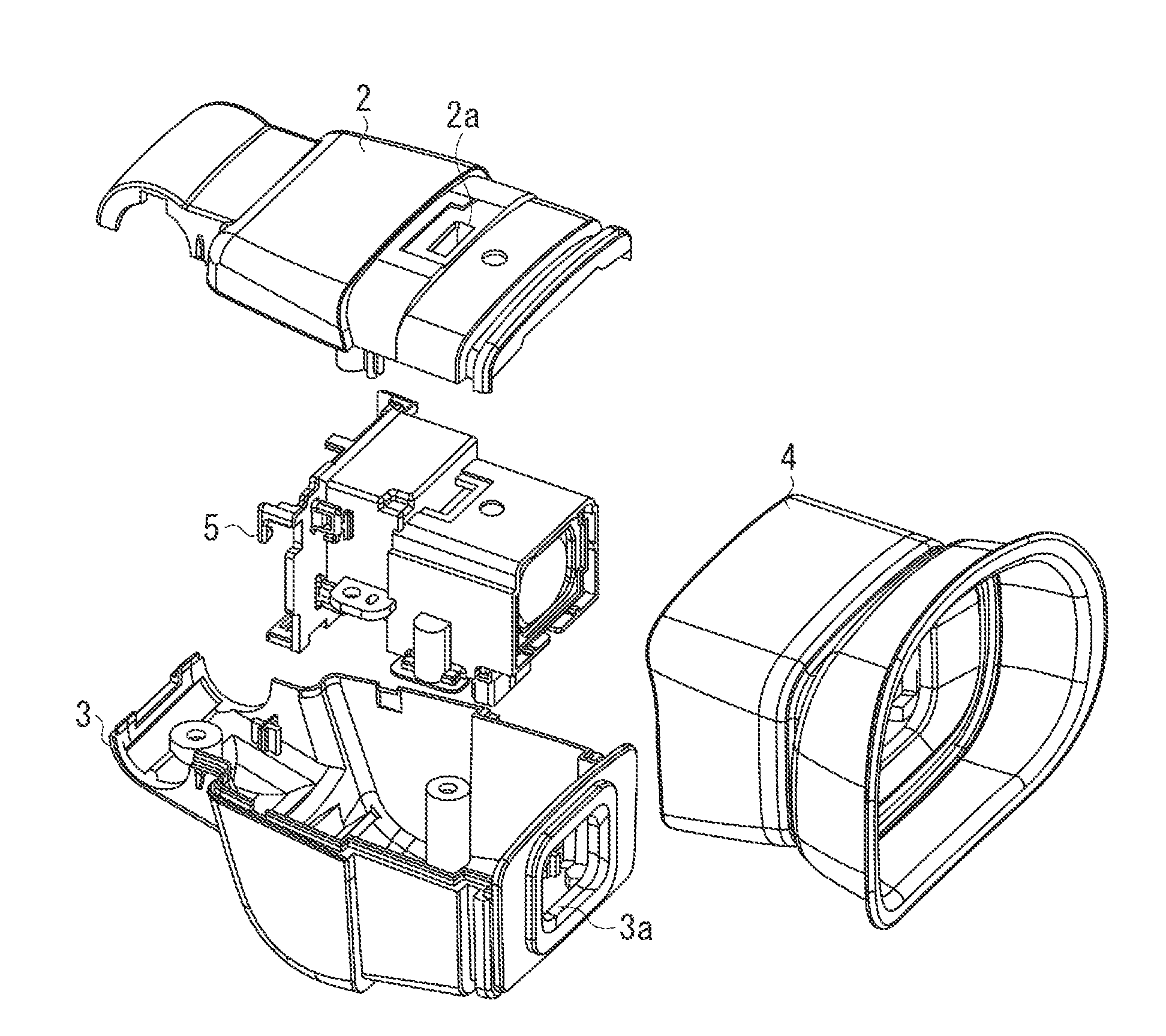
Figure 1 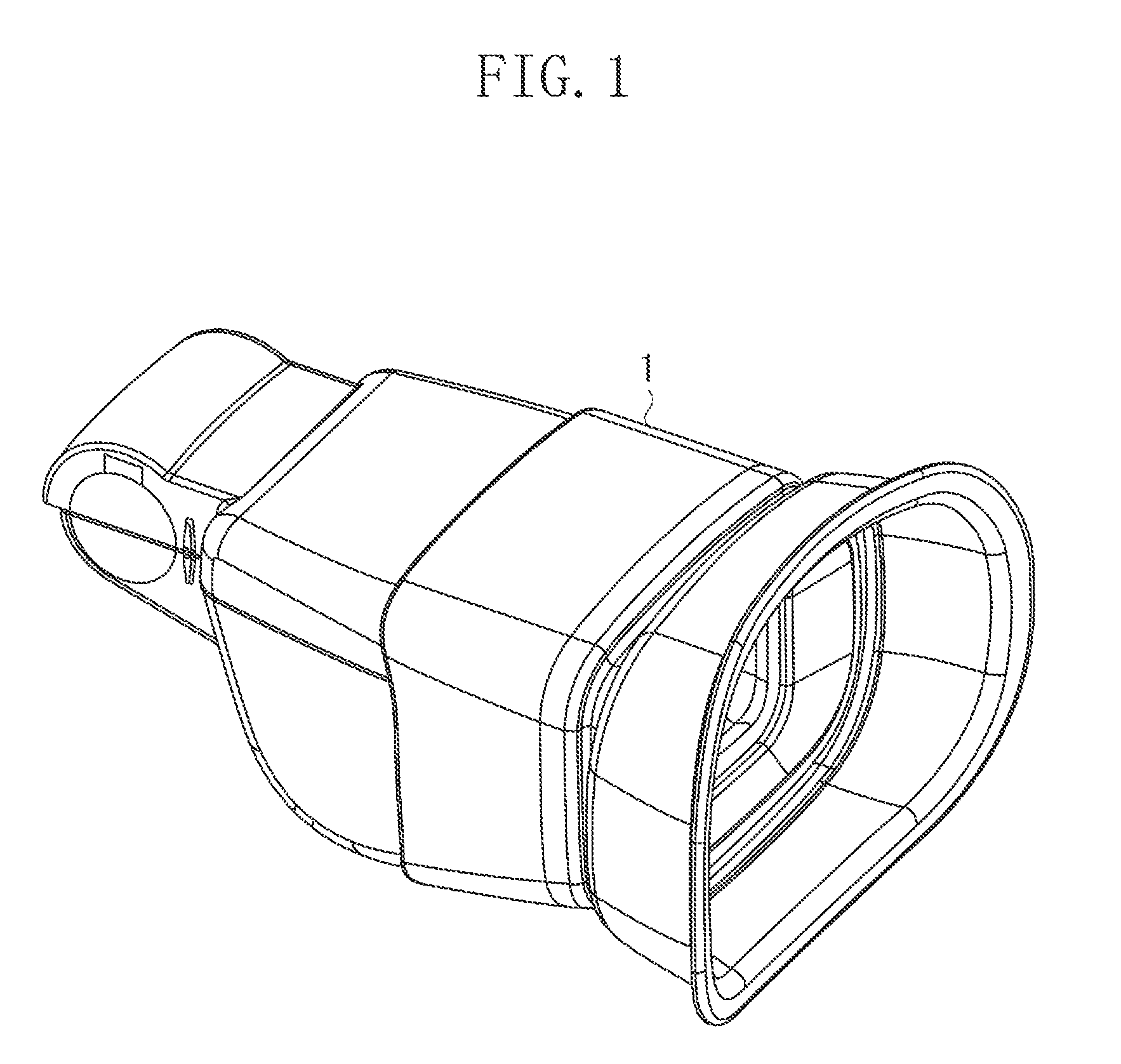
Figure 2 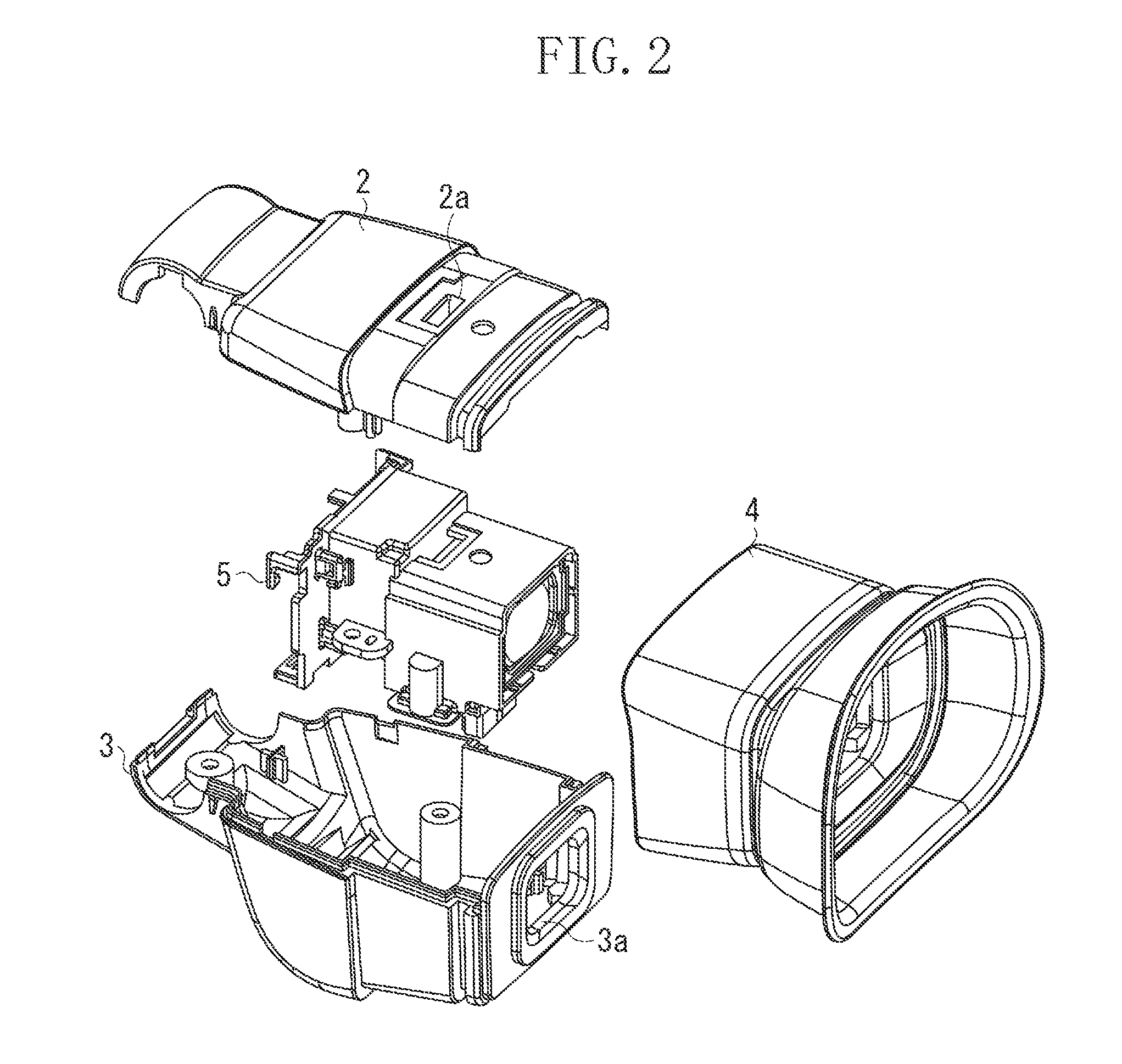
Figure 3
Abstract
Description
BACKGROUND OF THE INVENTION
[0001] 1. Field of the Invention
[0002] The present invention relates to an imaging apparatus, and, in particular, to an imaging apparatus equipped with a viewfinder.
[0003] 2. Description of the Related Art
[0004] Conventionally, the viewfinder of an imaging apparatus displays an image on a liquid crystal display unit based on a video signal during shooting. And, the image displayed on the liquid crystal display unit is enlarged at an eyepiece lens.
[0005] However, any foreign matter such as dust adhering to the interior of the viewfinder hinders the observation of the image. In view of this, as is known in the art, a dust-proof glass is provided between the eyepiece lens and the eyepiece opening to seal up the interior of the viewfinder. Further, Japanese Patent Application Laid-Open No. 5-68189 discusses a construction in which the dust-proof glass is arranged in an inclined state so that the external light may not be reflected by the dust-proof glass.
[0006] Howe...
Examples
Embodiment Construction
[0028]Various exemplary embodiments, features, and aspects of the invention will be described in detail below with reference to the drawings.
[0029]FIG. 16 is an external perspective view of a video camera constituting an example of an imaging apparatus to which the present invention is applied. As illustrated in FIG. 16, the video camera is equipped with a viewfinder 1.
[0030]FIG. 1 is an external perspective view of the viewfinder 1. As illustrated in FIGS. 1 and 16, in the present exemplary embodiment, the upper, lower, right-hand, and left-hand sides of the viewfinder 1 as seen from the observer side will be defined as the upper, lower, right-hand, and left-hand sides of the imaging apparatus.
[0031]FIG. 2 is an exploded perspective view of the viewfinder 1.
[0032]The viewfinder 1 is constructed such that a viewfinder assembly 5 is covered with an upper cover 2, a lower cover 3, and an eyecup 4 that is attachable / detachable by the observer. An opening 2a is formed in the upper cover...