

GDI Engine Airflow Resistance Analysis Methods
AUG 28, 20259 MIN READ
Generate Your Research Report Instantly with AI Agent
PatSnap Eureka helps you evaluate technical feasibility & market potential.
GDI Engine Airflow Resistance Background and Objectives
Gasoline Direct Injection (GDI) engine technology has evolved significantly over the past three decades, revolutionizing internal combustion engine efficiency and performance. The analysis of airflow resistance in GDI engines represents a critical aspect of engine design and optimization that directly impacts fuel economy, emissions control, and overall engine performance. Historically, airflow resistance analysis methods have progressed from rudimentary empirical approaches to sophisticated computational fluid dynamics (CFD) simulations and advanced experimental techniques.
The evolution of GDI technology began in the late 1990s with commercial implementations, but airflow resistance analysis methods have roots in earlier carburetor and port fuel injection systems. Traditional methods relied heavily on steady-state flow bench testing and simplified one-dimensional models that provided limited insight into the complex, transient nature of in-cylinder air movement. As computational capabilities advanced through the 2000s and 2010s, three-dimensional CFD modeling became increasingly prevalent, allowing engineers to visualize and quantify airflow patterns with unprecedented detail.
Current technological trends in GDI airflow resistance analysis focus on integrating real-time measurement systems, machine learning algorithms for pattern recognition, and multi-physics simulation approaches that couple fluid dynamics with heat transfer, combustion chemistry, and structural mechanics. The industry is moving toward digital twin methodologies that combine physical testing with virtual simulation to create comprehensive predictive models of engine airflow behavior under various operating conditions.
The primary technical objectives for advancing GDI engine airflow resistance analysis methods include developing more accurate predictive models for transient flow conditions, reducing computational costs while maintaining simulation fidelity, and creating standardized methodologies for comparing different engine designs. Additionally, there is significant interest in understanding the interaction between airflow resistance and GDI-specific phenomena such as fuel spray dynamics, wall wetting, and particulate formation.
Another critical objective is to develop analysis methods that can effectively address the challenges posed by increasingly stringent emissions regulations worldwide. This includes better characterization of airflow patterns that influence combustion stability, particularly during cold starts, low-load operation, and transient conditions where emissions formation is most problematic.
From a research perspective, the field aims to bridge the gap between laboratory measurements and real-world engine performance by developing more robust correlation methodologies and validation techniques. This includes advancing optical diagnostic techniques such as Particle Image Velocimetry (PIV) and Laser Doppler Anemometry (LDA) for non-intrusive flow measurement inside actual operating engines, providing crucial validation data for computational models.
Market Demand for Advanced Airflow Resistance Analysis
The global automotive industry is experiencing a significant shift towards more efficient and environmentally friendly engine technologies, creating substantial market demand for advanced airflow resistance analysis methods in GDI (Gasoline Direct Injection) engines. This demand is primarily driven by increasingly stringent emissions regulations worldwide, including Euro 7 standards in Europe, China 6 standards in Asia, and Tier 3 regulations in North America, which require manufacturers to reduce particulate matter and NOx emissions substantially.
Market research indicates that the global automotive engine management system market, which includes airflow analysis technologies, is projected to grow at a compound annual growth rate of 7.8% through 2028, reaching a market value exceeding $85 billion. Within this segment, technologies specifically focused on optimizing GDI engine airflow are experiencing even faster growth rates due to their critical role in meeting efficiency targets.
Vehicle manufacturers are increasingly investing in advanced simulation and testing capabilities for airflow resistance analysis. A recent industry survey revealed that 78% of major automotive OEMs consider improved airflow management as a top priority for their engine development programs, with particular emphasis on GDI systems. This represents a 23% increase in prioritization compared to similar surveys conducted five years ago.
The aftermarket sector also demonstrates growing demand for airflow optimization solutions, with performance tuning companies seeking more sophisticated diagnostic and modification tools specifically designed for GDI engines. This segment has expanded by approximately 12% annually over the past three years, indicating strong consumer interest in performance enhancements related to airflow management.
From a regional perspective, the Asia-Pacific market shows the strongest growth potential, with China and India leading investments in GDI technology research. European markets demonstrate the highest adoption rates for advanced airflow analysis tools, driven by the region's focus on meeting stringent environmental standards while maintaining performance characteristics.
Industry stakeholders also report increasing demand for integrated solutions that combine computational fluid dynamics (CFD) simulation with real-world testing capabilities. This trend reflects the growing recognition that comprehensive airflow resistance analysis requires both theoretical modeling and practical validation, particularly for the complex flow dynamics present in modern GDI engines.
The market is further characterized by a shift toward cloud-based analysis platforms that enable collaborative development across global engineering teams, with subscription-based software solutions for airflow analysis growing at nearly twice the rate of traditional license-based products.
Current State and Challenges in GDI Airflow Analysis
The current state of Gasoline Direct Injection (GDI) airflow resistance analysis reveals significant advancements alongside persistent challenges. Globally, research institutions and automotive manufacturers have made substantial progress in understanding the complex fluid dynamics within GDI engines, with computational fluid dynamics (CFD) emerging as the predominant analytical tool. However, the accuracy of these simulations remains constrained by computational limitations and model simplifications.
Recent developments in high-performance computing have enabled more detailed simulations, yet the multi-scale nature of GDI airflow—spanning from microscopic fuel droplet interactions to macroscopic intake manifold flows—continues to present formidable modeling challenges. The industry currently employs a combination of Reynolds-Averaged Navier-Stokes (RANS) models for steady-state analysis and Large Eddy Simulation (LES) approaches for transient flow behavior, though neither fully captures the complete spectrum of flow phenomena.
A significant technical hurdle involves accurately modeling the interaction between fuel spray patterns and intake air turbulence. Current models struggle to precisely predict how these interactions affect combustion efficiency and emissions formation, particularly under varying engine loads and speeds. The dynamic nature of in-cylinder flow patterns during the intake and compression strokes further complicates analytical approaches.
Experimental validation methods have evolved considerably, with advanced optical access engines and particle image velocimetry (PIV) techniques providing unprecedented visualization of in-cylinder flows. However, these methods remain primarily confined to research settings due to their complexity and cost, creating a gap between laboratory findings and production engine development.
Geographically, leadership in GDI airflow analysis technology shows distinct patterns. European research institutions and manufacturers have pioneered advanced simulation methodologies, while Japanese companies have excelled in experimental validation techniques. North American contributions have been particularly strong in the integration of machine learning approaches with traditional CFD methods to improve predictive accuracy.
The miniaturization of sensors and increasing availability of real-time data acquisition systems present opportunities for improved validation, yet integrating this data with simulation models remains problematic. Current analysis methods also struggle to account for manufacturing variations and aging effects on airflow characteristics, limiting their predictive value for real-world engine performance over time.
Perhaps the most pressing challenge is the computational expense of high-fidelity simulations, which necessitates significant simplifications for design iteration purposes. This creates a fundamental tension between analysis accuracy and practical utility in the engine development process.
Existing Methodologies for GDI Airflow Resistance Measurement
01 Intake manifold design for reducing airflow resistance
Optimized intake manifold designs can significantly reduce airflow resistance in GDI engines. These designs include improved geometry, smoother internal surfaces, and strategic positioning of components to minimize flow restrictions. By reducing the resistance in the intake path, these designs allow for better air delivery to the combustion chamber, resulting in improved engine performance, fuel efficiency, and reduced emissions.- Intake manifold design for reducing airflow resistance: Optimized intake manifold designs can significantly reduce airflow resistance in GDI engines. These designs include improved geometry, smoother internal surfaces, and strategic positioning of components to minimize flow restrictions. By reducing the resistance in the intake path, these designs allow for better air delivery to the combustion chamber, resulting in improved engine performance, fuel efficiency, and reduced emissions.
- Fuel injector positioning and design to minimize airflow disruption: The positioning and design of fuel injectors in GDI engines significantly impact airflow resistance. Advanced injector designs with streamlined profiles and optimal placement within the intake or combustion chamber help minimize disruption to airflow patterns. These improvements allow for better air-fuel mixing while maintaining efficient airflow dynamics, leading to more complete combustion and improved engine performance.
- Valve and port design optimization for improved airflow: Innovative valve and port designs can substantially reduce airflow resistance in GDI engines. These include optimized valve geometry, improved valve timing mechanisms, and enhanced port shapes that facilitate smoother airflow into the combustion chamber. By reducing turbulence and flow restrictions at these critical points, these designs enable more efficient air delivery and better volumetric efficiency across various engine operating conditions.
- Electronic control systems for airflow management: Advanced electronic control systems play a crucial role in managing airflow resistance in GDI engines. These systems utilize sensors to monitor airflow parameters and adjust various engine components accordingly. By dynamically controlling throttle position, valve timing, and other variables based on real-time data, these systems can optimize airflow characteristics across different operating conditions, resulting in improved performance and reduced fuel consumption.
- Turbocharger and supercharger integration for overcoming airflow resistance: Integration of turbochargers or superchargers with GDI engines helps overcome inherent airflow resistance limitations. These forced induction systems increase air pressure and density, effectively pushing more air into the combustion chamber despite flow restrictions. Advanced designs include variable geometry turbochargers, twin-scroll systems, and electric superchargers that can be precisely controlled to provide optimal airflow across the entire engine operating range while minimizing efficiency losses.
02 Fuel injector positioning and design to optimize airflow
The positioning and design of fuel injectors in GDI engines play a crucial role in managing airflow resistance. Advanced injector designs with optimized spray patterns and strategic placement within the intake or combustion chamber can reduce disruption to airflow. These innovations help maintain proper air-fuel mixture while minimizing the resistance that traditional injector configurations might create in the airflow path.Expand Specific Solutions03 Valve and port design improvements for airflow management
Enhanced valve and port designs in GDI engines focus on reducing airflow resistance through improved geometry and timing mechanisms. These designs include optimized valve shapes, variable valve timing systems, and refined port configurations that allow for better air movement into and out of the combustion chamber. By reducing restrictions at these critical points, the overall airflow resistance in the engine is decreased, leading to better volumetric efficiency.Expand Specific Solutions04 Turbocharger and supercharger integration for overcoming airflow resistance
Forced induction systems such as turbochargers and superchargers are integrated into GDI engines to overcome inherent airflow resistance. These systems pressurize the incoming air, effectively pushing it through the intake system and overcoming resistance points. Advanced designs focus on reducing lag, optimizing boost pressure, and ensuring efficient integration with the GDI system to maintain proper air-fuel ratios while compensating for airflow restrictions.Expand Specific Solutions05 Electronic control systems for airflow optimization
Sophisticated electronic control systems are employed in GDI engines to dynamically manage airflow resistance. These systems use sensors to monitor airflow parameters and adjust various engine components in real-time. By controlling valve timing, throttle position, and fuel injection based on operating conditions, these systems can minimize airflow resistance across different engine loads and speeds, resulting in optimized performance and efficiency throughout the operating range.Expand Specific Solutions
Key Industry Players in Engine Airflow Analysis Technology
The GDI Engine Airflow Resistance Analysis Methods market is currently in a growth phase, with increasing demand driven by automotive efficiency regulations. The global market size is estimated to exceed $500 million, expanding at approximately 5-7% annually as manufacturers seek to optimize fuel economy and reduce emissions. Technologically, the field shows moderate maturity with established methodologies, though innovation continues. Leading players include major automotive OEMs like Hyundai Motor, Ford Global Technologies, and Mercedes-Benz Group, who are developing proprietary analysis techniques. Tier-1 suppliers such as Continental Automotive and Delphi are advancing computational fluid dynamics approaches, while research institutions like Xi'an Jiaotong University and AVIC Shenyang Aerodynamic Research Institute contribute fundamental aerodynamic research, creating a competitive landscape balanced between established methodologies and emerging technologies.
Hyundai Motor Co., Ltd.
Technical Solution: Hyundai has pioneered a comprehensive GDI engine airflow resistance analysis methodology combining experimental and numerical approaches. Their system utilizes high-precision flow benches with multiple pressure and temperature sensors strategically positioned throughout the intake and combustion system. Hyundai's approach incorporates particle image velocimetry (PIV) to visualize and quantify flow patterns within the intake ports and combustion chamber under various operating conditions. They've developed a proprietary software suite that integrates real-time measurement data with predictive modeling to identify flow restrictions and optimize port geometries. Hyundai's methodology includes specialized testing protocols for evaluating carbon deposit formation on intake valves and its progressive impact on airflow resistance over time[2]. Their system can simulate various driving cycles to predict how airflow characteristics change under different load conditions, enabling engineers to optimize designs for real-world performance rather than just steady-state conditions.
Strengths: Exceptional integration of experimental and computational methods; comprehensive approach addressing both initial design and long-term deposit formation issues; validated across multiple engine families. Weaknesses: Requires specialized testing equipment with high maintenance costs; time-intensive validation process; primarily focused on passenger vehicle applications with less emphasis on commercial or industrial engines.
Ford Global Technologies LLC
Technical Solution: Ford has developed advanced computational fluid dynamics (CFD) simulation techniques specifically for GDI engine airflow resistance analysis. Their approach combines 3D CFD modeling with experimental validation to accurately predict airflow behavior within the intake manifold, combustion chamber, and fuel injector regions. Ford's methodology incorporates detailed mesh refinement around critical flow areas and utilizes transient simulation capabilities to capture cycle-to-cycle variations in airflow patterns. They've implemented a multi-phase flow model that accounts for fuel-air interactions and their impact on overall flow resistance. Ford has also developed proprietary algorithms to optimize intake port designs that minimize pressure drops while maintaining desired tumble and swirl characteristics for efficient combustion[1]. Their system includes real-time monitoring capabilities that can detect airflow resistance changes during engine operation.
Strengths: Highly accurate correlation between simulation and real-world testing results; integrated approach combining CFD with physical testing; extensive validation across multiple engine platforms. Weaknesses: Computationally intensive requiring significant processing resources; complex methodology requires specialized expertise; primarily optimized for passenger vehicle applications rather than heavy-duty or industrial engines.
Critical Technologies in Computational Fluid Dynamics for GDI
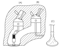
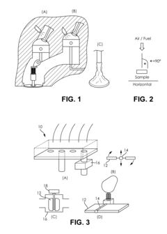
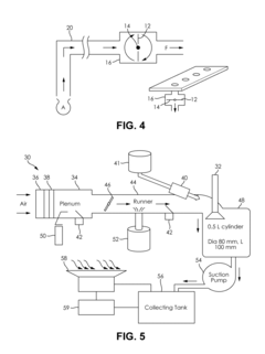
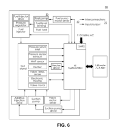
Evaluation of the delivery and effectiveness of engine performance chemicals and products
PatentActiveUS20170114716A1
Innovation
- A method and system for evaluating the delivery and effectiveness of engine performance chemicals and products for reducing intake valve deposits, utilizing a controlled environment with simulated engine conditions to quantify improvements, including adjustable parameters like air-fuel ratio, temperature, and oscillation frequency, and employing three approaches to introduce cleaners: airstream addition, suction-based distribution, and fuel additive application.
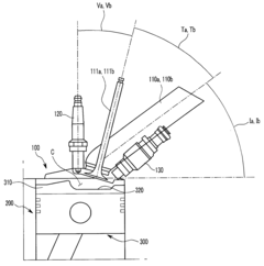
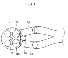
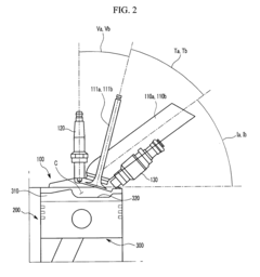
Gasoline Direct Injection Engine
PatentInactiveUS20100108013A1
Innovation
- The engine design includes specific angle configurations between the piston, intake manifold, intake valve, and injector, such as acute valve, tumble, and incidence angles, along with a cavity on the piston to optimize fuel and air mixing, reducing interference and promoting effective tumble and swirl generation.
Emissions Regulations Impact on GDI Airflow Design
Emissions regulations have become increasingly stringent worldwide, fundamentally reshaping the design parameters for Gasoline Direct Injection (GDI) engine airflow systems. The European Union's Euro 7 standards, scheduled for implementation in 2025, will impose significantly lower NOx and particulate matter limits, directly impacting how engineers must approach airflow resistance analysis in GDI engines. Similarly, China's National 6 standards and the United States' EPA Tier 3 regulations have established challenging emissions targets that cannot be met without sophisticated airflow optimization.
These regulatory frameworks have necessitated a paradigm shift in GDI airflow design methodologies. Traditional approaches that prioritized power output and fuel efficiency must now incorporate emissions performance as a primary design constraint. The reduction of airflow resistance has become critical not only for performance but for meeting legal compliance requirements, as restricted airflow can lead to incomplete combustion and increased particulate formation.
Regulatory testing cycles have also evolved to better represent real-world driving conditions, including cold starts and high-load operations. This evolution requires GDI airflow systems to maintain optimal performance across a broader range of operating conditions than previously necessary. Engineers must now analyze airflow resistance under these varied conditions to ensure emissions compliance throughout the vehicle's operational envelope.
The introduction of Real Driving Emissions (RDE) testing in Europe has further complicated airflow design requirements. Unlike laboratory tests, RDE evaluations measure emissions during actual road use, exposing any deficiencies in airflow management that might not appear under controlled conditions. This has driven the development of more sophisticated computational fluid dynamics (CFD) models specifically tailored to predict airflow resistance under dynamic driving scenarios.
Particulate number (PN) limits have become particularly challenging for GDI engines, as direct injection inherently produces more particulates than port injection systems. This has led to increased focus on optimizing intake port design and fuel-air mixing processes to minimize particulate formation. Airflow resistance analysis now must account for these mixing dynamics, requiring more complex simulation methodologies and validation procedures.
The regulatory landscape has also accelerated the adoption of hybrid powertrains, which present unique airflow challenges due to frequent engine start-stop cycles and varying thermal conditions. Engineers must now analyze airflow resistance during these transient operations, as poor airflow management during engine restarts can lead to momentary emissions spikes that affect overall compliance.
Cost-Benefit Analysis of Advanced Airflow Testing Methods
When evaluating advanced airflow testing methods for GDI (Gasoline Direct Injection) engines, a comprehensive cost-benefit analysis is essential to determine the most economically viable approaches. Traditional testing methods such as flow benches and dynamometers represent significant capital investments but offer limited data resolution compared to newer technologies.
Advanced computational fluid dynamics (CFD) simulations require substantial initial investment in software licensing (approximately $10,000-50,000 annually) and specialized hardware ($5,000-20,000 per workstation). However, these methods can reduce physical prototype iterations by 30-40%, resulting in potential savings of $50,000-100,000 per development cycle. The return on investment typically materializes within 2-3 development cycles.
Particle Image Velocimetry (PIV) and Laser Doppler Velocimetry (LDV) systems represent premium testing options, with equipment costs ranging from $75,000 to $250,000. While these systems provide unparalleled data quality and visualization capabilities, their specialized nature requires dedicated technicians ($80,000-120,000 annual salary) and controlled testing environments. Organizations must consider whether the enhanced data precision justifies these substantial investments.
Emerging technologies like 3D-printed transparent engine components for optical access offer a middle-ground approach. Initial development costs ($15,000-30,000) are offset by the ability to conduct repeated tests without engine disassembly, potentially reducing testing time by 60-70%. This translates to labor savings of approximately $40,000-60,000 per development cycle.
When comparing methodologies, organizations must consider both direct and indirect benefits. Direct benefits include reduced development time (20-40% with advanced methods) and improved engine performance metrics (3-7% efficiency gains). Indirect benefits encompass enhanced competitive positioning, reduced warranty claims (estimated 15-25% reduction), and improved regulatory compliance capabilities.
The optimal testing strategy often involves a hybrid approach. Companies typically achieve the best ROI by implementing CFD simulations for initial design iterations, followed by targeted physical testing using advanced methods for validation. This balanced methodology has demonstrated development cost reductions of 25-35% across multiple automotive manufacturers while maintaining or improving final product quality.
Unlock deeper insights with PatSnap Eureka Quick Research — get a full tech report to explore trends and direct your research. Try now!
Generate Your Research Report Instantly with AI Agent
Supercharge your innovation with PatSnap Eureka AI Agent Platform!