Signal polarity detection device and associated method

A signal polarity and detection device technology, applied in the direction of electromagnetic field characteristics, can solve the problems of components affecting the correction results, phase imbalance, and failure to meet the requirements of wireless radio frequency signal receivers, etc.

CN101113997AInactive Publication Date: 2008-01-30MSTAR SEMICON INC
0 Cites 0 Cited by

Patent Information

Authority / Receiving Office
CN · China
Current Assignee / Owner
Publication Date
2008-01-30
Estimated Expiration
Not applicable · inactive patent

Smart Images

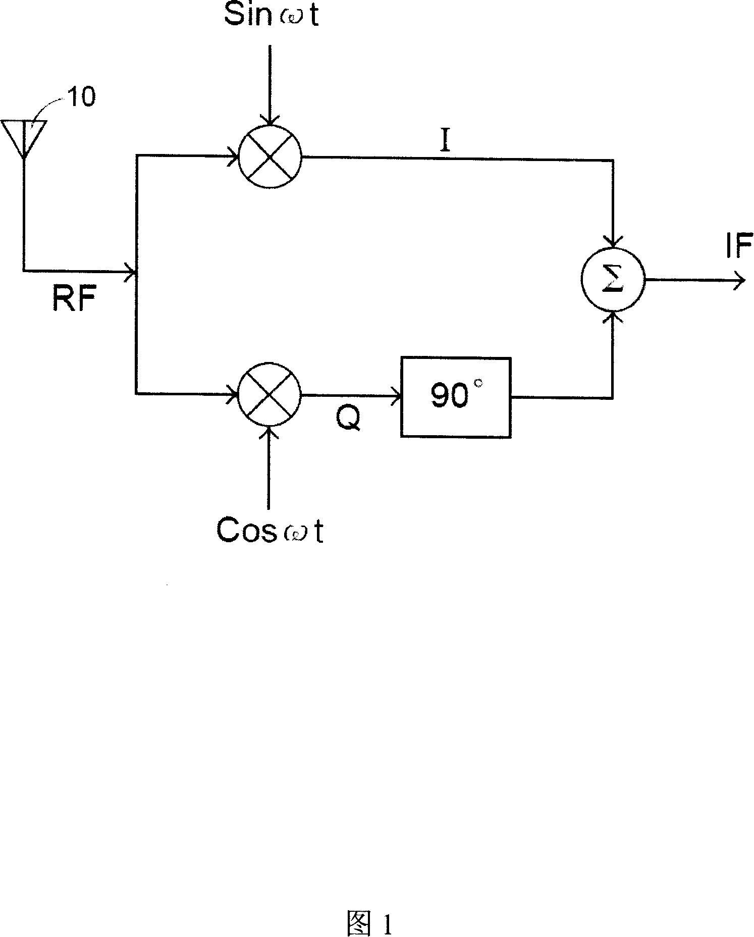
  • Figure 1
    Figure 1
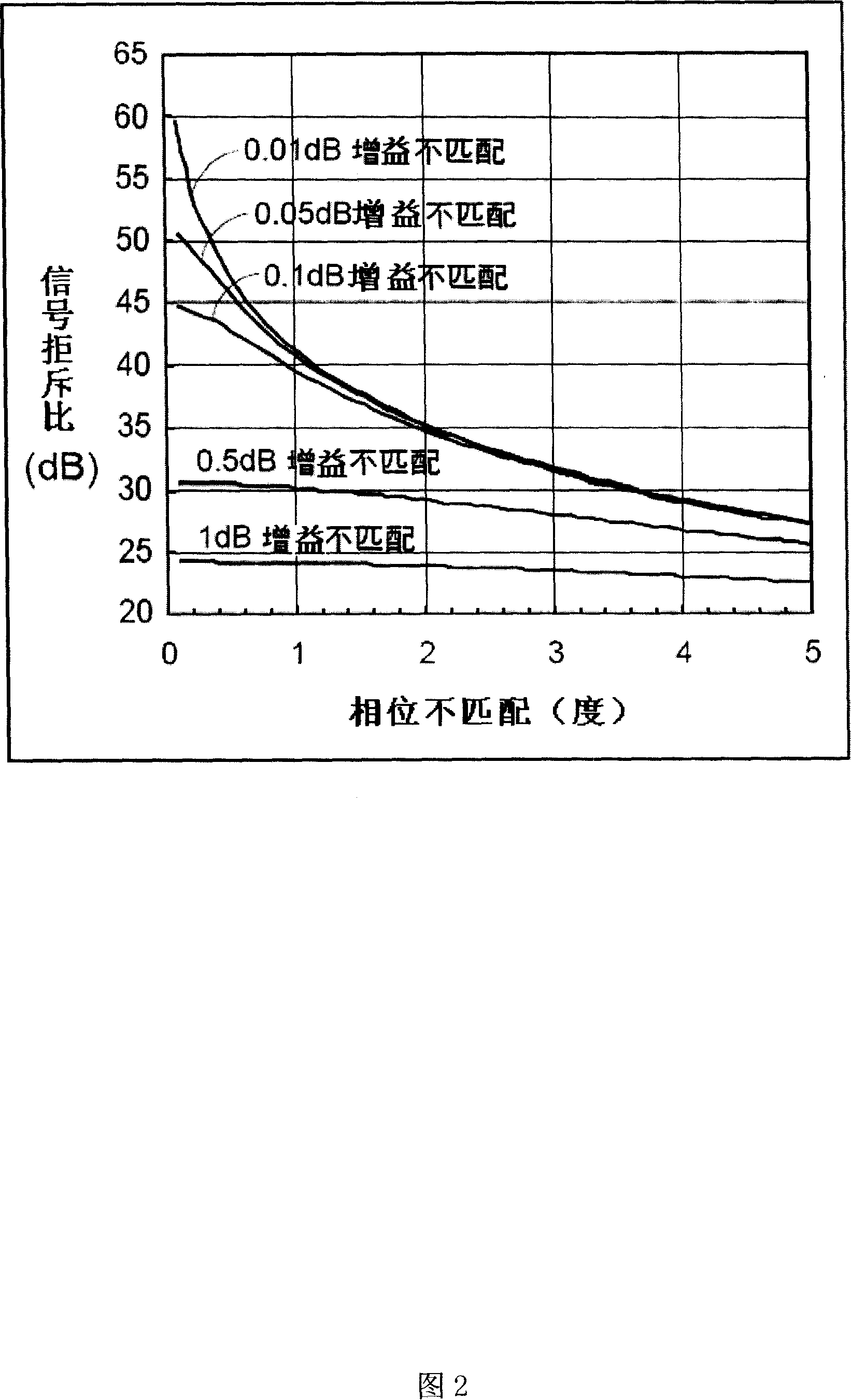
  • Figure 2
    Figure 2
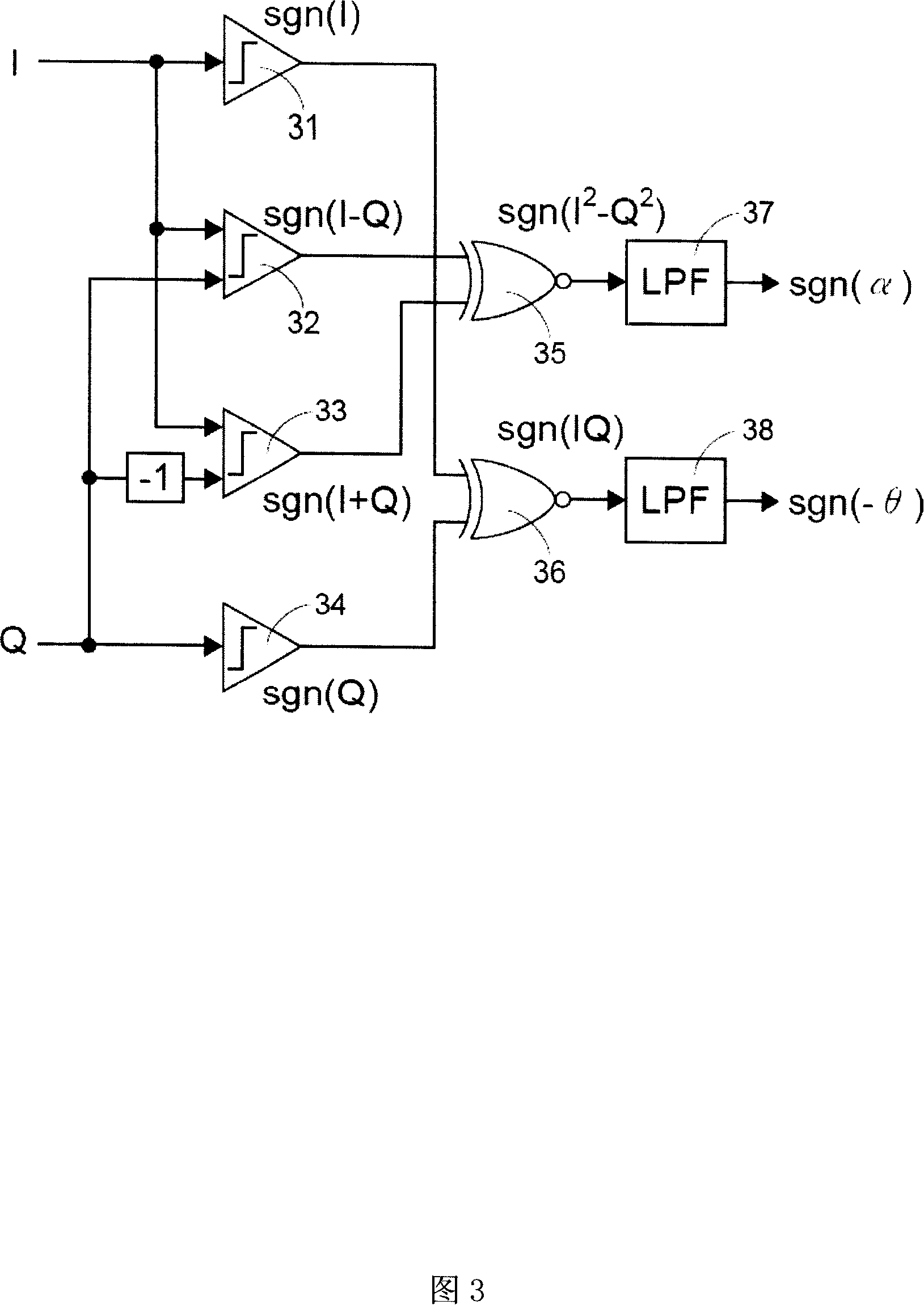
  • Figure 3
    Figure 3
Patent Text Reader

Abstract

The invention discloses a signal polarity detection device and method. The signal polarity detection device includes: a first comparison device, a second comparison device and an arithmetic unit. The first comparison device is used to respond to a first time period Comparing a first signal with a first threshold signal with a second period to output a first output signal; the second comparison device is used for comparing a second signal with a second threshold signal to output a third output signal, which changes the polarity of the third output signal corresponding to the first period and the second period; A polarity data of the second signal product.
Need to check novelty before this filing date? Find Prior Art

Description

technical field

[0001] The invention relates to a signal polarity detection device and method, especially a detection device and method for detecting the multiplicative polarity of two input signals. Background technique

[0002] Quadrature Signals (Quadrature Signals) I / Q generation has been widely used in various wireless signal transmissions, and can be implemented with a quadrature down-conversion mixer or a polyphase filter. In non-zero-IF receiver architectures, quadrature signal I / Q is important for post-frequency conversion image signal cancellation; in zero-IF receiver architectures, quadrature signal I / Q can be used in noncoherent demodulation (noncoherent demodulation). As shown in the block diagram of the wireless signal receiving end in Figure 1, after the radio frequency wireless signal RF is received by the antenna 10, it is multiplied by the sinusoidal signal Sinωt and the Cosωt signal respectively, and then demodulated to generate an in-phase (In-phase) sig...

Examples

Embodiment Construction

[0045] FIG. 3 shows a functional block diagram for detecting an imbalance between a signal I and a signal Q. Referring to FIG. Assuming that α represents the gain mismatch value, and θ represents the phase mismatch value, and when α is much smaller than 1 and θ is small, the signal I and signal Q can be expressed by the following formulas:

[0046] I=(1+α)cos(ωt+θ)

[0047] Q=sin(ωt)

[0048] The product of signal I and signal Q can be expressed as:

[0049] I · Q = ( 1 + α ) cos ( ωt + θ ) · sin ( ωt )

[0050] = ( 1 + α ) ( cos ( ωt ) ...