Tortuous flow doubleeffect heating solar heat-collector air heat collectors

An air heat collector and baffled technology, which is applied to solar heat collectors, solar heat collectors using working fluids, solar thermal energy, etc. Unable to adjust according to needs, heating distance and time are short, etc., to achieve the effect of reduced heat loss, long heating time, and small impact

Inactive Publication Date: 2008-05-14
HENAN SENGDA ENERGY ENVIRONMENTAL PROTECTION
View PDF0 Cites 21 Cited by
  • Summary
  • Abstract
  • Description
  • Claims
  • Application Information

AI Technical Summary

Problems solved by technology

Regardless of the structure, when the air enters the heat collector, it is directly discharged from the heat collector and sent to the place where hot air is needed after being heated once in a single pass. Due to the limitation of the structure and specifications of the heat collector, The heatable distance and time of the air flowing through the collector are relatively short, and it cannot absorb heat to the maximum extent, so the temperature rise of the air after one cycle is small; in addition, the hot air in this type of collector is naturally Flowing, the circulation speed is too slow, and the system temperature cannot be adjusted according to the needs, which is mostly inconvenient to use
It can be seen that the heat collection rate of the above-mentioned air collector has not been maximized, and it cannot collect and gain heat to the greatest extent.

Method used


Image

  • Tortuous flow doubleeffect heating solar heat-collector air heat collectors
  • Tortuous flow doubleeffect heating solar heat-collector air heat collectors

Examples


Embodiment Construction

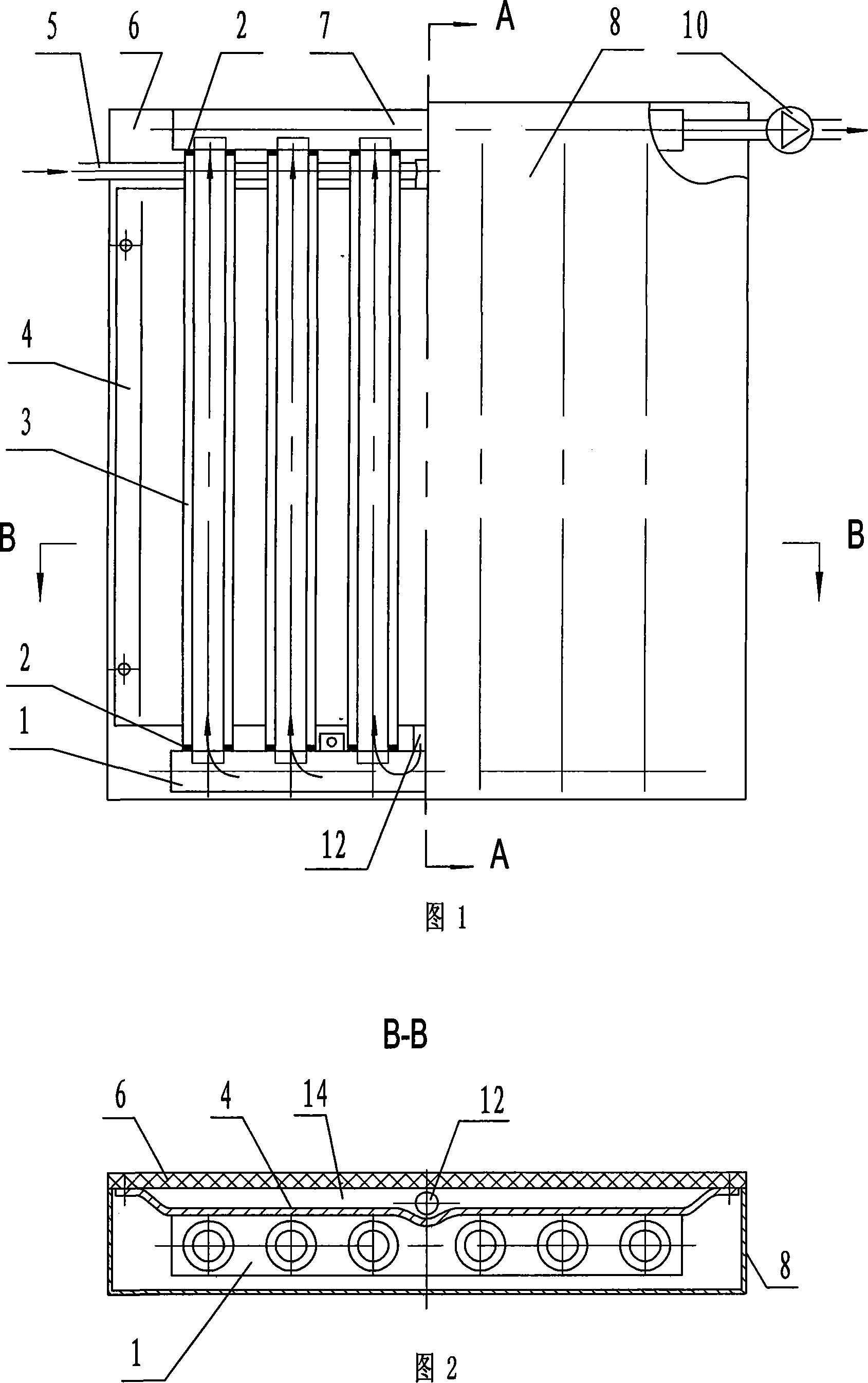
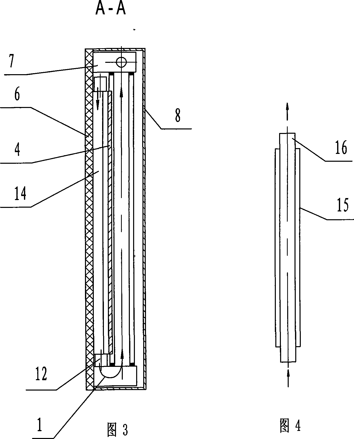
[0020] The baffle type double-effect heating solar air heat collector shown in Fig. 1-Fig. 4 comprises heat preservation bottom plate 6 and the heat collector core installed on the heat preservation bottom plate, is also installed on the heat preservation bottom plate to buckle the heat collector core The glass cover body 8 forms a closed space between the glass cover body 8 and the thermal insulation bottom plate 6 .

[0021] The heat collector core includes a heat-absorbing plate 4 installed on the heat-insulating bottom plate. The left and right sides of the heat-absorbing plate 4 are bent outwardly toward one side of the heat-insulating bottom plate 4 and then bent horizontally. The heat-absorbing plate 4 passes through its horizontal The bent part fits and is fixedly connected with the heat-insulating bottom plate 6; the upper and lower ends of the heat-absorbing plate 4 are provided with closed ends, and a closed heating air duct 14 is formed between the heat-absorbing pl...


PUM


Abstract

The invention relates to a flow-bending double-effect heating solar-energy air heat collecting device, comprising an insulation soleplate and a heat collecting device core. The heat collecting device core comprises a heat absorbing board arranged on the insulation soleplate, and a sealed heating air channel is arranged between the heat absorbing board and the insulation soleplate. A horizontal first air-feeding pipeline and a horizontal air-venting pipeline are arranged on the upper part of the heat absorbing board. A horizontal bottom bracket is arranged on the lower part of the heat absorbing board, and a sealed second air-feeding pipeline is arranged in the bottom bracket. Sealed heat collecting tubes are vertically arranged by intervals between the bottom bracket and the air-venting pipeline, and the heat collecting tubes are arranged on the upper part of the face of the heat absorbing board. The upper end and the lower end of the heating air channel are communicated with the corresponding first and second air-feeding pipelines. The upper end and the lower end of the heat collecting tube are communicated with the corresponding air-venting pipeline and the second air-feeding pipeline. A glass cover used for covering the heat collecting device core is arranged on the insulation soleplate. Through two-time heating, the heating distance of the structure is approximately raised by one time. And the heat absorbing efficiency is enhanced and the heating effect is reinforced. One-time circulation temperature rises more quickly.

Description

technical field [0001] The invention relates to the technical field of solar heat utilization, in particular to a solar air heat collector. Background technique [0002] At present, there are two types of solar air collectors commonly used: plate type and heat collecting tube type. The plate type heat collector is mainly composed of an insulating base plate with an insulating frame around it, a heat collecting plate core and a glass cover set on the insulating base plate. The heat collecting tube type heat collector is mainly composed of inlet and outlet pipes and several heat collecting tubes arranged side by side. Regardless of the structure, when the air enters the heat collector, it is directly discharged from the heat collector and sent to the place where hot air is needed after being heated once in a single pass. Due to the limitation of the structure and specifications of the heat collector, The heatable distance and time that the air flows through in the heat collec...

Claims


Application Information

Patent Timeline
Patent Type & Authority Applications(China)
IPC IPC(8): F24J2/05F24J2/46F24S10/40
CPCY02E10/44
Inventor 陈开碇冀小珍解志华徐洪阁
Owner HENAN SENGDA ENERGY ENVIRONMENTAL PROTECTION
Why Eureka
Try Eureka