Packing shaft seal structure of improved type vertical pump

A vertical pump, an improved technology, applied in the direction of non-variable-capacity pumps, pumps, pump components, etc., can solve the problems of water pump damage, poor water flow, inconvenient structural disassembly and assembly, etc.

Inactive Publication Date: 2009-08-19
HITACHI PUMP MFG WUXI
View PDF0 Cites 1 Cited by
  • Summary
  • Abstract
  • Description
  • Claims
  • Application Information

AI Technical Summary

Problems solved by technology

[0002] For existing vertical pump packing shaft seal structure, see figure 1 , which includes a pump shaft 8, a packing seat 1, a packing gland 4, a water seal ring 3, a bearing protection tube 7, and a pump cover 6. The packing seat 1 is set on the pump shaft 8, and the upper part of the packing seat 1 is pressed The packing gland 4 is installed, and the cavity surrounded by the packing seat 1, the packing gland 4 and the pump shaft 8 is equipped with a packing 2, and a water seal ring 3 is installed in the cavity, and the water seal ring 3 will The filler 2 installed in the cavity is divided into upper and lower parts, the water seal ring 3 is connected to the filler sealing water joint 5, the lower part of the filler seat 1 is fastened to the pump cover 3, and the pump cover 6 is connected to the bearing guard The pipe 7, the packing seat 1, the pump shaft 8,

Method used


Image

  • Packing shaft seal structure of improved type vertical pump
  • Packing shaft seal structure of improved type vertical pump

Examples


Embodiment Construction

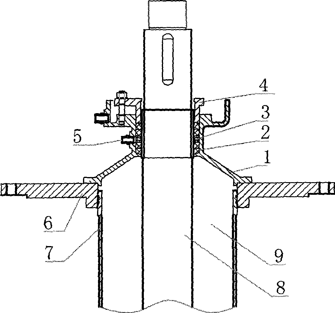
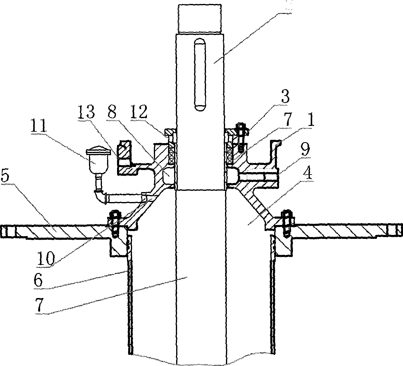
[0009] See figure 2 , the present invention includes a pump shaft 2, a packing seat 1, a packing gland 3, and a pump cover 5, the packing seat 1 is set on the pump shaft 2, the packing gland 3 is installed on the upper part of the packing seat 1, and the lower part of the packing seat 1 is fastened to the pump cover 5. The pump cover 5 is connected to the bearing protection tube 6. The packing seat 1, the pump shaft 2 and the bearing protection tube 6 form a cavity 4. The packing seat 1 is set on the pump shaft 2 to form two upper and lower annular cavities 7 and 8. The upper annular chamber 7 is filled with filler, the lower annular chamber 8 is connected to the water inlet 9, the water inlet 9 is located on the side of the packing seat 1, and the lower annular chamber 8 is connected to the cavity 4 through the gap between the packing seat 1 and the pump shaft 2, The air outlet hole 10 at the lower part of the stuffing seat 4 communicates with the cavity 4 . The air outlet ...


PUM


Abstract

The invention relates to a modified vertical pump stuffing shaft gland structure, which smoothly discharges air in the interior of a hollow cavity while meeting the cooling stuffing and a pump spindle and can be dismantled conveniently. The structure comprises the pump spindle, a stuffing seat, a stuffing gland cover, and a pump cover. The stuffing seat is sheathed in the pump spindle. The upper part of the stuffing seat is provided with the stuffing gland cover and the lower part of the stuffing seat is fixedly connected with the pump cover which is connected with a bearing protecting tube. The stuffing seat, the pump spindle, and the bearing protecting tube form a cavity. The structure is characterized in that the stuffing seat is sheathed on the pump spindle to form an upper annular chamber and a low annular chamber; the upper annular chamber is filled with stuffing; the low annular chamber is filled with pressure water and communicated with the cavity by a clearance between the stuffing seat and the pump spindle; an air outlet at the lower part of the stuffing seat is communicated with the cavity.

Description

(1) Technical field [0001] The invention relates to the field of water supply and drainage equipment, in particular to an improved packing shaft seal structure of a vertical pump. (2) Background technology [0002] For existing vertical pump packing shaft seal structure, see figure 1 , which includes a pump shaft 8, a packing seat 1, a packing gland 4, a water seal ring 3, a bearing protection tube 7, and a pump cover 6. The packing seat 1 is set on the pump shaft 8, and the upper part of the packing seat 1 is pressed The packing gland 4 is installed, and the cavity surrounded by the packing seat 1, the packing gland 4 and the pump shaft 8 is equipped with a packing 2, and a water seal ring 3 is installed in the cavity, and the water seal ring 3 will The filler 2 installed in the cavity is divided into upper and lower parts, the water seal ring 3 is connected to the filler sealing water joint 5, the lower part of the filler seat 1 is fastened to the pump cover 3, and the pu...

Claims


Application Information

Patent Timeline
IPC IPC(8): F04D29/10
Inventor 李龙江朱泉荣赵艳
Owner HITACHI PUMP MFG WUXI
Why Eureka
Try Eureka