Freezing apparatus, and expander

A technology of refrigeration device and expansion mechanism, which is applied in refrigerators, safety devices, gas cycle refrigerators, etc., and can solve the problems of low recovery efficiency

Active Publication Date: 2011-05-04
DAIKIN IND LTD
View PDF6 Cites 0 Cited by
  • Summary
  • Abstract
  • Description
  • Claims
  • Application Information

AI Technical Summary

Problems solved by technology

[0008] However, as mentioned above, injecting high-pressure refrigerant into the expansion mechanism during the expansion stroke, or making the refrigerant bypass the expansion mechanism, although the refrigerant circulation of the compression mechanism and the expansion mechanism is balanced, it can be recovered to the maximum extent. The energy of the dynamic high-pressure refrigerant can only be partially recovered by the expansion mechanism, which is not the desired configuration from the perspective of recovery efficiency.

Method used


Image

  • Freezing apparatus, and expander
  • Freezing apparatus, and expander
  • Freezing apparatus, and expander

Examples


no. 1 approach

[0136] -Overall configuration of the air conditioner-

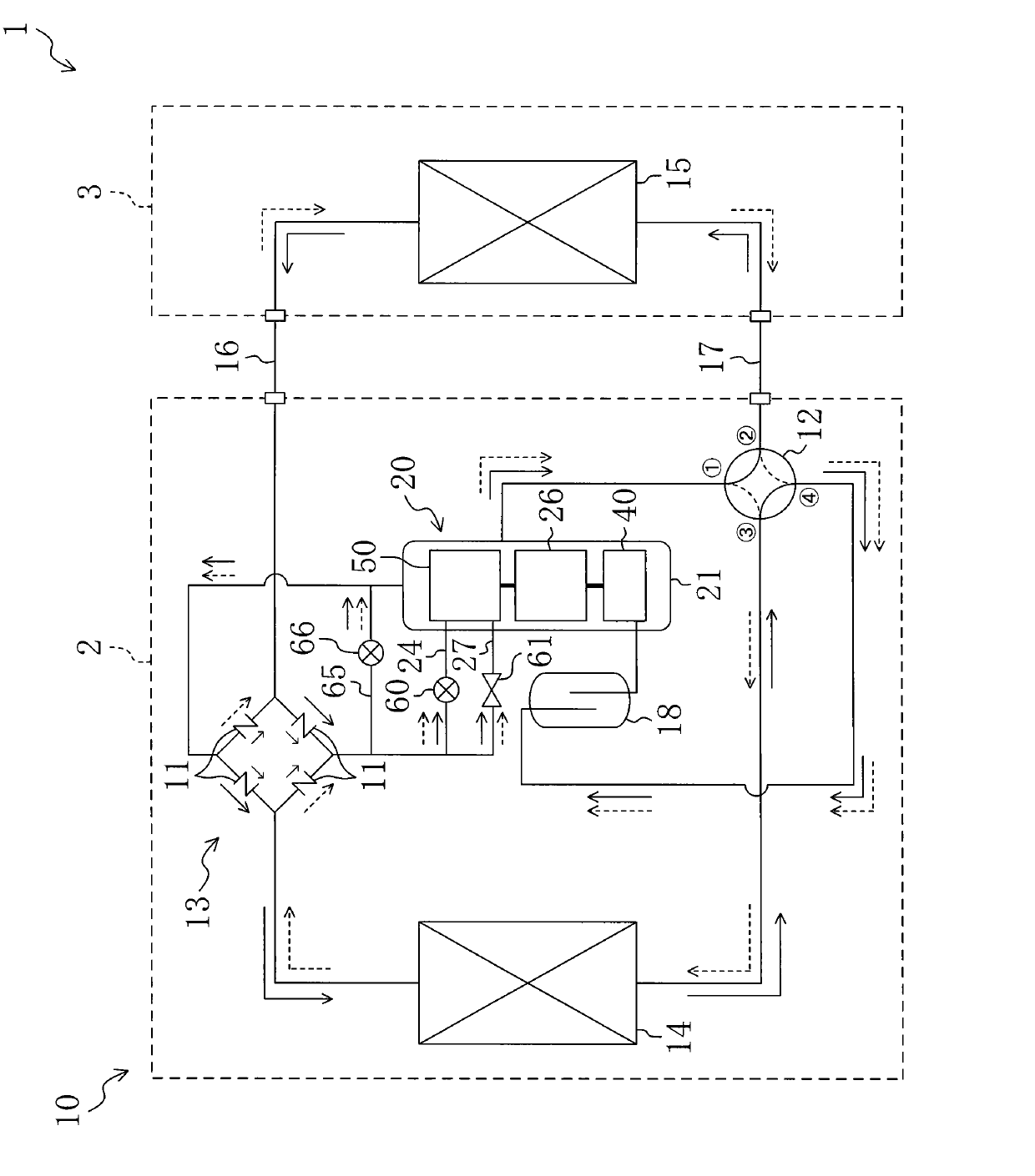
[0137] figure 1 In , the refrigerant circuit 10 of the air-conditioning apparatus 1 serving as a refrigeration apparatus according to the first embodiment of the present invention is shown. This air conditioner 1 includes an outdoor unit 2 and an indoor unit 3 . The outdoor unit 2 is provided with a compression expansion unit 20 , an outdoor heat exchanger 14 , a four-way reversing valve 12 , and a bridge circuit section 13 composed of check valves 11 , 11 , 11 , 11 . On the other hand, the indoor unit 3 is provided with an indoor heat exchanger 15 . In addition, although not shown in particular, each of the heat exchangers 14 and 15 is provided with a fan, and outdoor air and indoor air are blown to each of the heat exchangers 14 and 15 in this structural state.

[0138] The outdoor unit 2 and the indoor unit 3 communicate with each other through a pair of connecting pipes 16, 17, thereby forming the refrigerant circu...

no. 2 approach

[0249] Next, a second embodiment of the present invention will be described in detail based on the drawings. Such as Figure 15 As shown, the second embodiment differs from the above-mentioned first embodiment in that the expansion mechanism 50 is composed of two rotating mechanism parts 70 and 80 , and the expansion mechanism is constituted by a scroll mechanism 200 . Since the configuration other than the expansion mechanism is the same as that of the first embodiment, illustration and description thereof will be omitted.

[0250] Specifically, the scroll mechanism 200 includes a fixed scroll 220 fixed to a housing (not shown), and a movable scroll 210 supported to the housing through bearings (not shown).

[0251] The fixed scroll 220 constitutes a scroll component, including a plate-shaped fixed end plate (not shown), and a scroll-shaped fixed tooth 221 erected on the fixed end plate. On the other hand, the movable scroll 210 constitutes a scroll member and includes a fl...


PUM


Abstract

Provided is a freezing apparatus, which is constituted to make the inlet quantity of a coolant of an expansion mechanism variable while recovering the energy of a high-pressure coolant as a power to the maximum by the expansion mechanism. The expansion mechanism (50) is equipped with two rotary mechanism units (70 and 80) having displacements made different from each other. These rotary mechanismunits are connected in series, and the rotary mechanism unit of the smaller displacement has two inlet ports (55 and 56) formed in its cylinder (71). Inlet pipes (24 and 27), as connected to the inlet ports (55 and 56), are equipped with a front throttle valve (60) and a switch valve (61). A bypass pipe (65) for bypassing the expansion mechanism (50) is equipped with a bypass valve (66). These valves (60, 61 and 66) are controlled to attain a balance between the coolant circulation rate of the expansion mechanism (50) and the coolant circulation rate of a compression mechanism (40).

Description

technical field [0001] The present invention relates to a refrigeration device including an expansion mechanism, in particular to a volumetric expansion mechanism that generates power from the expansion of fluid. Background technique [0002] Conventionally, as disclosed in Patent Documents 1 and 2, in a refrigerant circuit that performs a refrigerating cycle, a refrigeration device is known that includes an expansion mechanism for recovering power from refrigerant together with a compression mechanism. The power recovered from the high-pressure refrigerant by the expansion mechanism is transmitted to the connected compression mechanism through the drive shaft, and is used to drive the compression mechanism. [0003] However, since the refrigerant circuit is a closed circuit, the amount of refrigerant circulating through the compression mechanism per unit time (equivalent to mass flow, the same below) must always be consistent with the amount of refrigerant circulating throu...

Claims


Application Information

Patent Timeline
Patent Type & Authority Patents(China)
IPC IPC(8): F01C21/18F01C1/02F01C1/356F01C11/00F01C13/04F01C20/18F01C20/24F25B1/00F25B11/02
CPCF01C11/004F01C1/322F01C13/04F01C20/02F01C20/26F01C21/06F01C21/104F01C21/18F04C18/322F04C18/324F04C23/008F04C23/02F04C29/124F25B1/04F25B9/008F25B9/06F25B13/00F25B2309/061F25B2313/0272F25B2313/02741F25B2400/0411F25B2600/2513
Inventor 鉾谷克己冈本昌和熊仓英二冈本哲也
Owner DAIKIN IND LTD
Why Eureka
Try Eureka