Injection molding zipper

A technology of zipper and chain elements, which is applied in the field of zippers, can solve the problem of insufficient bonding force between injection molded zipper elements and cloth tape, and achieve the effect of improving the bonding force

Inactive Publication Date: 2010-06-09
崔逸泉
View PDF0 Cites 16 Cited by
  • Summary
  • Abstract
  • Description
  • Claims
  • Application Information

AI Technical Summary

Problems solved by technology

[0005] The purpose of the present invention is to overcome the defect of insufficient binding force between the injection molded zipper elements and the cloth tape in the above-mentioned prior art, and provide a new type of injection molded zipper, which fundamentally changes the injection molded zipper elements. The combination method with the zipper tape, that is, the way in which the injection molding material wraps the center line of the core area of ​​the zipper tape, so that the bonding force between the injection molded zipper elements and the zipper tape can be significantly improved

Method used


Image

  • Injection molding zipper
  • Injection molding zipper
  • Injection molding zipper

Examples


Embodiment 1

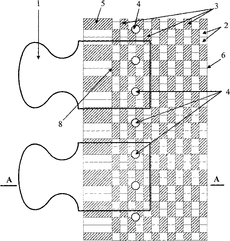
[0021] Such as figure 1 As shown, the injection molded zipper of the present invention comprises: chain element 1, cloth tape 6, and described cloth tape 6 is made up of central line 5, a group of warp threads 3 and continuous weft thread 2; cloth tape 6 contacts with chain element 1 and is drawn The part covered by the fastener element 1 is the joint surface area of ​​the tape 6, and the meridional continuous tape part of the joint surface is the core area 8 of the tape 6, and a row of edges is set beside the center line 5 in the core area 8. The small holes 4 evenly distributed in the direction of the warp 3, and the spacing of the small holes 4 ensure that there are at least one or more small holes 4 in the joint surface area between the cloth tape 6 and each individual fastener element 1 . The injection molding material liquid heated and melted by the injection molding machine in the production process of the injection molding zipper is extruded by the screw of the injecti...

Embodiment 2

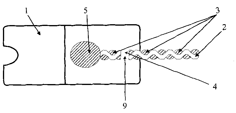
[0024] Such as image 3 As shown, the central line 5 in the core region 8 of the cloth tape 6 in the injection molded zipper of the present invention is thinned, and the number of warps 3 in the core region 8 of the injection molded zipper cloth 6 is increased, and in the core region of the cloth tape 6 Two or more rows of evenly distributed small holes 4 are arranged in a staggered arrangement in the direction of the warp 3 in 8, and the spacing of the small holes 4 ensures that there are at least two or two The above small holes 4; in this way, there are at least two plastic columns 9 in the joint surface area of ​​each element 1 of the injection molded zipper and the cloth tape 6 after production; the bonding force of the elements 1 of the injection molded zipper and the cloth tape 6 will be greater. promote. Other unmentioned specific structures of the injection molded zipper in this embodiment are the same as those in Embodiment 1 of the present invention.

Embodiment 3

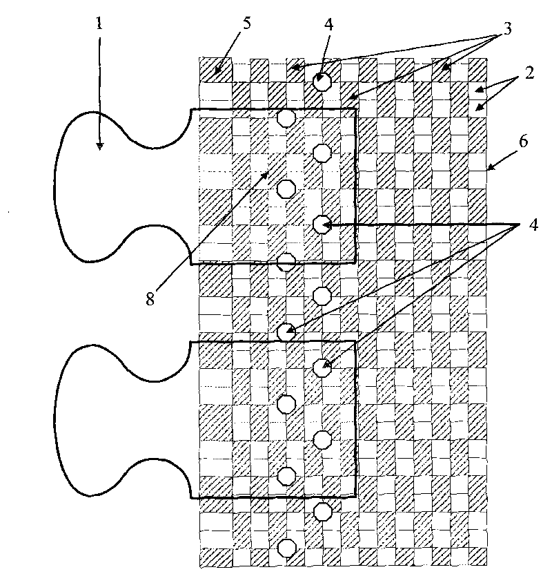
[0026] Such as Figure 4 As shown, the cloth tape 6 in the injection molded zipper of the present invention is not provided with a center line 5, and a row or two or more rows of evenly distributed small Hole 4, the interval between small holes 4 ensures that there is at least one or more small holes 4 in the joint surface area between cloth tape 6 and each fastener element 1; in this way, each fastener element 1 of the injection molded zipper is combined with cloth tape 6 after production. There are at least one or more plastic material columns 9 in the surface area. Other unmentioned specific structures of the injection molded zipper in this embodiment are the same as those in Embodiment 1 of the present invention.


PUM


Abstract

The invention aims to overcome the defect of insufficient binding force between the zipper teeth and the strap of the injection molding zipper in the prior art, and provides an injection molding zipper in a novel structure. In the injection molding zipper of the invention, the strap in the binding face region between the zipper teeth and the strap is provided with a small hole, at least one small hole or more than more small holes is / are arranged in the binding face region between the strap and each single zipper tooth, and the small holes are uniformly distributed in the arrangement direction of the zipper teeth. The small holes can ensure the injection molding material liquid, which is melted by the injection molding machine, to pass through in the production process of the injection molding zipper, so that the injection molding material liquid forms molding upright posts in the small holes after being cooled, and the molding upright posts and the zipper teeth can form an integral body. The injection molding zipper of the invention fundamentally changes the binding mode between the zipper teeth and the zipper strap of the injection molding zipper, which means to change the mode of the injection molding material wrapping the central line in the binding face region of the zipper strap, thereby obviously enhancing the binding force between the zipper teeth and the zipper strap of the injection molding zipper.

Description

technical field [0001] The invention relates to a zipper, in particular to an injection molded zipper, also known as a plastic steel zipper. Background technique [0002] Injection molded zippers on the market are composed of cloth tape and chain teeth. The cloth tape is woven from a center line, a set of ordinary warp threads and a continuous weft thread; the center line is also called the rib of the zipper tape, which is the most The thick warp thread is composed of a group of yarns; the common warp thread is mostly polyester low-stretch yarn, with about 50 or more threads. The meridional continuous tape part of the joint surface of the tape and the chain element is the core area of ​​the tape, which contains the center line and part of the warp, while the rest of the warp is distributed outside the joint surface of the tape and the chain element; The teeth are in the state of individual particles and are evenly spaced, clamping the relatively thick centerline of the clot...

Claims


Application Information

Patent Timeline
Patent Type & Authority Applications(China)
IPC IPC(8): A44B19/02
Inventor 崔逸泉
Owner 崔逸泉
Why Eureka
Try Eureka