Electric winding body and transformer having forced cooling

A technology for electrical windings and transformers, applied in the field of transformers, can solve problems such as the inability to provide structural space for transformers, and achieve the effects of good cooling, improved cooling, and extended working life.

Inactive Publication Date: 2010-08-18
SIEMENS AG
View PDF2 Cites 5 Cited by
  • Summary
  • Abstract
  • Description
  • Claims
  • Application Information

AI Technical Summary

Problems solved by technology

[0006] The disadvantage of these solutions known from the prior art is that a large number of components have to be arranged around the transformer or installed in the transformer station for this purpose
According to the solutions known from the prior art, the provision of cooling ducts for existing transformers, especially cast resin transformers, is only possible with a number of structural measures and in many cases no corresponding structural space can be provided around the transformer

Method used


Image

  • Electric winding body and transformer having forced cooling
  • Electric winding body and transformer having forced cooling
  • Electric winding body and transformer having forced cooling

Examples


Embodiment Construction

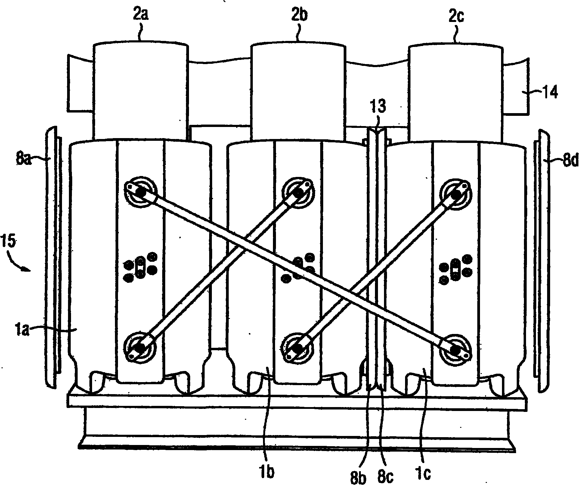
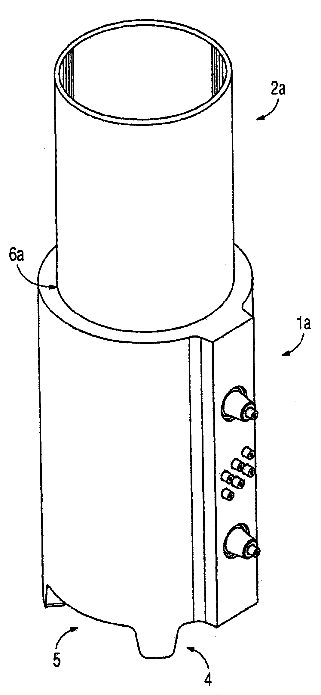
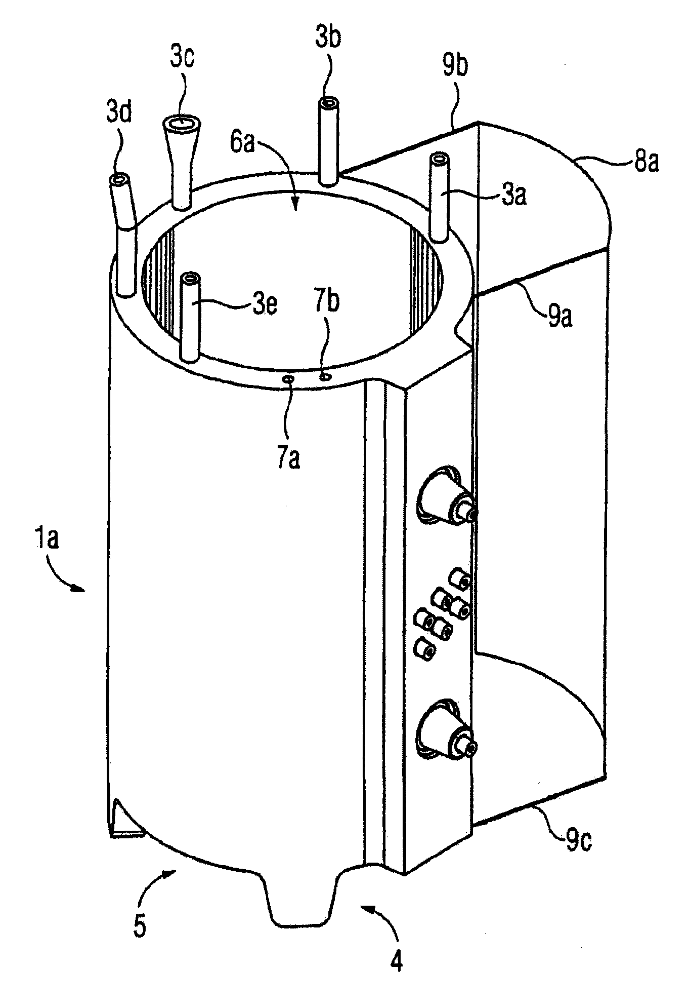
[0039] FIG. 1 shows a perspective view of an electrical winding body 1a with a base 4 forming a gap 5 below the electrical winding body 1a. Air can flow from below through the gap 5 into the through channels 10a, 10b, 10c (10a not shown). A magnetizable iron core (not shown) is inserted into the through central channel 10a of the electrical winding body 1a, so that the electrical winding body 1a can be used as a component of a transformer. An extension part 2 a , which is designed, for example, in the shape of a cylinder, can be inserted into the through channel 10 a. Coolant, in particular air, can escape from the electrical winding body 1 a through holes in the upper part of the cylinder. Air enters one of the through-channels 10 a to 10 c via the gap 5 and exits the bore of the extension 2 a by means of the chimney effect. The influence of the flow and convection conditions directly above the end faces of the electrical winding body 1 a is largely reduced or prevented by ...


PUM


Abstract

The invention relates to an electric winding body (1a, 1b, 1c) comprising an electrically conductive winding and an insulation surrounding the winding, wherein the surrounding insulation surrounds the entire winding and forms a mechanically stable winding body, and wherein inside the winding body at least one continuous channel having an opening in the electric winding body is arranged. By arranging an elongation element (2a, 2b, 2c) in the openings of the continuous channels, the channels are elongated beyond the dimensions of the electric winding body, thus providing for improved cooling. By attaching additional lateral elements (8a, 8b, 8c, 8d) on the outer wall of the electric winding body, the intermediate space created in this way forms a new cooling channel, which produces an additional cooling effect due to the air current created by the chimney effect.

Description

technical field [0001] The invention relates to an electrical winding body with an electrically conductive winding and an insulator surrounding the winding, wherein the annular insulator surrounds the entire winding and forms a mechanically stable winding body, and at least one through passage is arranged inside the electrical winding body, The channels have holes provided in the body of the electrical winding. Furthermore, the invention relates to a transformer having an electrical winding body according to the invention. The electrical winding body is an integral part of the transformer. Background technique [0002] The thermal load of transformers, especially resin cast transformers, greatly affects the service life of transformers. Therefore, especially for air-cooled transformers, such as cast-resin transformers, sufficient cooling of the windings is necessary. [0003] For example, EP0092204A2 describes an induction coil in which, according to the invention, coolin...

Claims


Application Information

Patent Timeline
Patent Type & Authority Applications(China)
IPC IPC(8): H01F27/08H01F27/28H01F27/32
CPCH01F27/322H01F27/085H01F27/327H01F27/324H01F27/2876
Inventor 鲁道夫·哈诺夫弗里茨·索格
Owner SIEMENS AG
Why Eureka
Try Eureka