Drawer-type ecological combined building block and ecological body made of same
What is AI technical title?
AI technical title is built by PatSnap AI team. It summarizes the technical point description of the patent document.
An ecological combination and drawer-type technology, applied in horticulture, botany equipment and methods, container cultivation, etc., can solve the problems of waste of land, no greening, no greening of walls or columns, etc., and achieve small footprint and low cost , good effect of greening
Pending Publication Date: 2010-09-08
孙希贤
View PDF1 Cites 11 Cited by
Summary
Abstract
Description
Claims
Application Information
AI Technical Summary
This helps you quickly interpret patents by identifying the three key elements:
Problems solved by technology
Method used
Benefits of technology
Problems solved by technology
[0002] There is no greening on traditional walls or columns, and creepers are usually used for greening. Roads are isolated by steel structures, cement piers or wide green belts, and railways are isolated by barbed wire and walls. The disadvantages are no greening and waste of land.
The patent CN2914640 ecological block can only be greened on one side, and the axis of the planting hole is parallel to the ground, and the inside is small and the outside is large. When it rains heavily, it will wash away the flowers and soil and lose its effect
Method used
Image
Click on the blue label to locate the original text in one second.
Reading with bidirectional positioning of images and text.
Examples
Embodiment 2
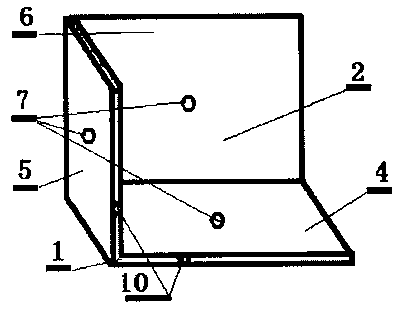
[0049] Example 2: see image 3 , Figure 4 , Figure 51 , Figure 52 , Figure 53 , Figure 54 , Figure 55 , Figure 56 , Figure 57 , Figure 58 , Example 2 is basically the same as Example 1, except that there is a hexahedron 6 connecting the horizontal plate 4 and the vertical plate 5 at the rear of the base body 1 in Example 2.
Embodiment 3
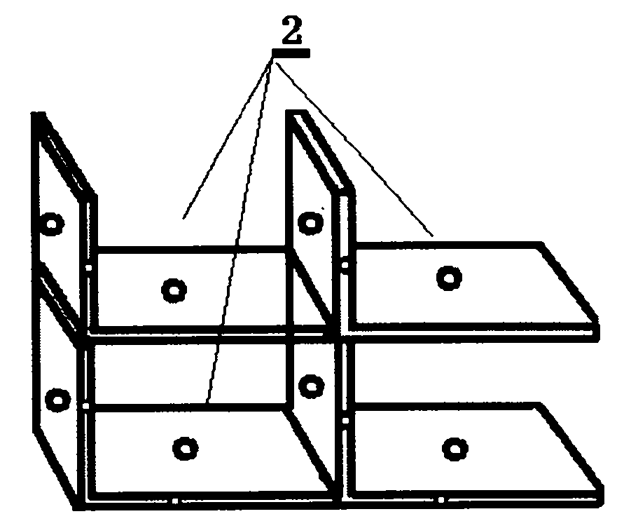
[0050] Embodiment 3: see Figure 5 , Figure 6 , Figure 51 , Figure 52 , Figure 53 , Figure 54 , Figure 55 , Figure 56 , Figure 57 , Figure 58 , Figure 59 , Figure 60 , Figure 61 , Figure 62 , Example 3 is basically the same as Example 1, except that the matrix 1 in Example 3 is composed of two vertical plates 5 and one horizontal plate 4, and the angle between the two vertical plates 5 is 0 to 30 degrees, and the connection method A vertical plate 5 is connected to a horizontal plate 4, and a horizontal plate 4 is connected to another vertical plate 5.
Embodiment 4
[0051] Embodiment 4: see Figure 7 , Figure 8 , Figure 51 , Figure 52 , Figure 53 , Figure 54 , Figure 55 , Figure 56 , Figure 57 , Figure 58 , Figure 59 , Figure 60 , Figure 61 , Figure 62 , Example 4 is basically the same as Example 1, except that the matrix 1 in Example 4 is composed of three vertical plates 5 and two horizontal plates 4, and the angle between the two vertical plates 5 is 0 to 30 degrees, and the connection method Connect the first horizontal plate 4 for the first vertical plate 5, the first horizontal plate 4 connects the second vertical plate 5, the second vertical plate 5 connects the second horizontal plate 4, and the second horizontal plate Plate 4 is connected to a third vertical plate 5 .
PUM
Abstract
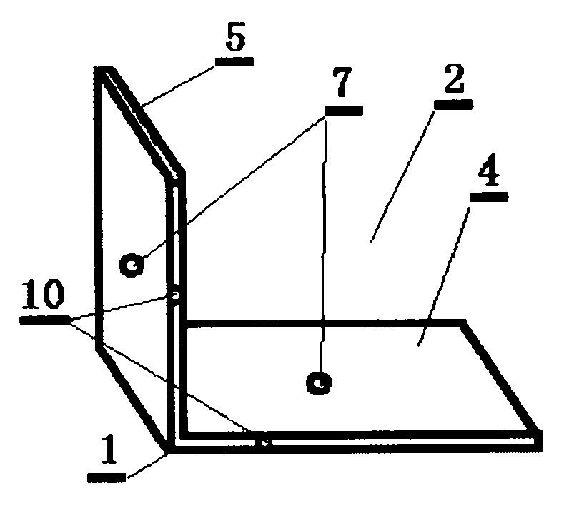
The invention relates to a green facility, in particular to a drawer-type ecological combined building block and an ecological body made of the same. The drawer-type ecological combined building block comprises matrixes 1 and a drawer cavity 2 and a flower soil container 3 which are arranged in the matrix 1. The drawer-type ecological combined building block is characterized in that horizontal plates 4 and vertical plates 5 are connected mutually to form the matrix 1; the matrixes 1 are piled up to form the drawer cavity 2, and the flower soil container 3 extending out of the drawer cavity 2 is arranged in the drawer cavity 2. In the drawer-type ecological combined building block and the ecological body made of the same, soil can be directly put in the flower soil container 3, and then flowers and plants are planted in the soil, and thereby, the goal of planting plants in the drawer-type ecological combined building block and the ecological body can be achieved.
Description
technical field [0001] The invention relates to a greening facility, in particular to a drawer-type ecological combination block on which plants are planted and an ecological body built thereon. Background technique [0002] The traditional wall or column has no greening, and creepers are usually used for greening. Roads are isolated by steel structures, cement piers or wide green belts, and railways are isolated by barbed wire and walls. The disadvantages are that there is no greening and waste of land. Patent CN2914640 ecological block, it can only be greened on one side, and the axis of the planting hole is parallel to the ground, and the inside is small and the outside is large. When it rains heavily, the flowers, grass and soil will be washed away and lose its effect. In the present invention, the flower soil container is placed in the drawer cavity of the ecological body built with drawer-type ecological combination blocks, and then flowers and plants are planted in th...
Claims
Application Information
Patent Timeline
Application Date:The date an application was filed.
Publication Date:The date a patent or application was officially published.
First Publication Date:The earliest publication date of a patent with the same application number.
Issue Date:Publication date of the patent grant document.
PCT Entry Date:The Entry date of PCT National Phase.
Estimated Expiry Date:The statutory expiry date of a patent right according to the Patent Law, and it is the longest term of protection that the patent right can achieve without the termination of the patent right due to other reasons(Term extension factor has been taken into account ).
Invalid Date:Actual expiry date is based on effective date or publication date of legal transaction data of invalid patent.

