Self-locking type steel pipe fence

A self-locking, steel pipe technology, applied in the direction of fences, building types, buildings, etc., can solve problems such as troublesome operation

Inactive Publication Date: 2010-09-08
WUXI SHUANGQIANG ELECTRIC DOOR MFG
View PDF5 Cites 0 Cited by
  • Summary
  • Abstract
  • Description
  • Claims
  • Application Information

AI Technical Summary

Problems solved by technology

The effect of this device is better, but it is cumbersome to operate, especiall...

Method used


Image

  • Self-locking type steel pipe fence
  • Self-locking type steel pipe fence
  • Self-locking type steel pipe fence

Examples


Embodiment Construction

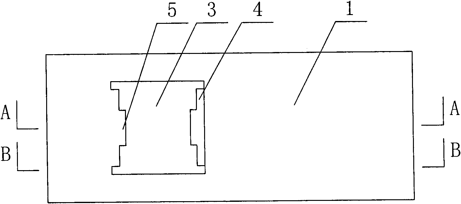
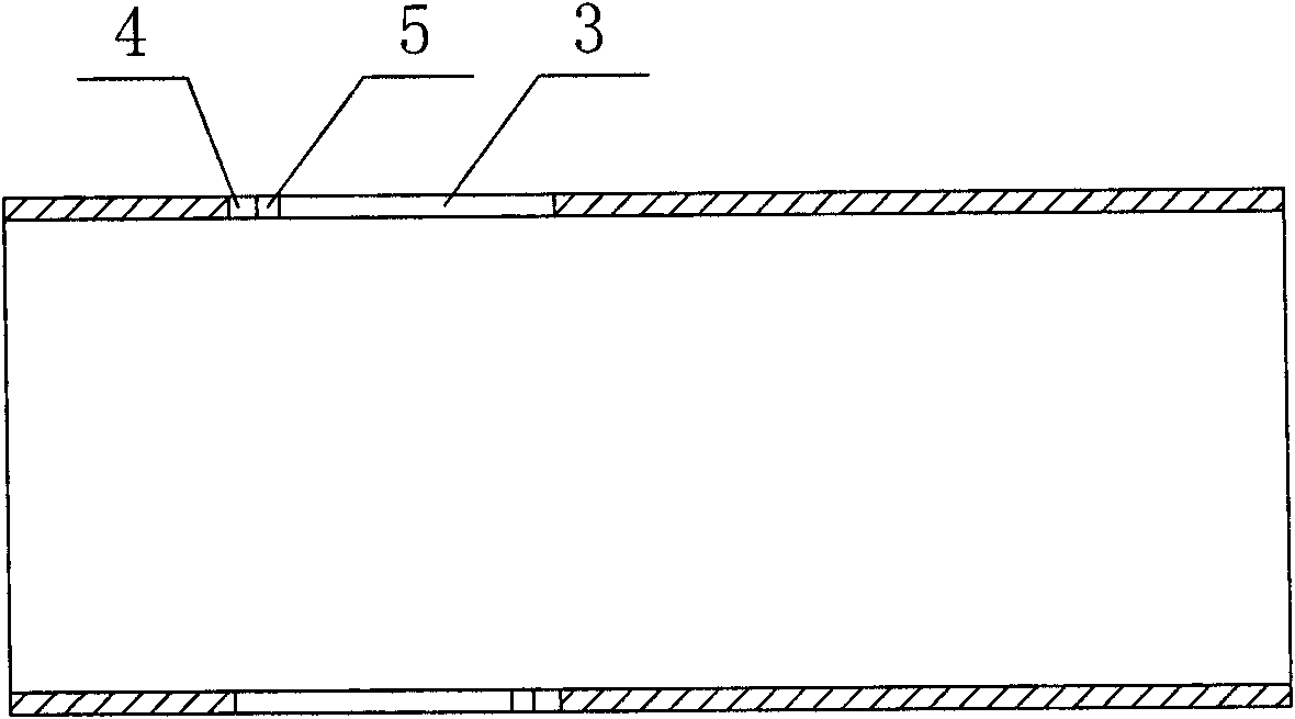
[0030] like Figure 1-6 As shown in the figure, a self-locking steel pipe fence includes a horizontal bar 1 and a vertical bar 2, and the vertical bar 2 is inserted into the hole 3 on the horizontal bar 1, on the two diagonal sides of the hole 3 on the horizontal bar 1. Supporting bosses 4 are respectively provided, and a tongue 5 is arranged at the front end of each boss 4. The width of the tongue 5 is smaller than the width of the boss 4, and the length of the protrusion of the boss 4 is greater than the length of the protrusion of the tongue 5. The distance of the boss 4 in the horizontal direction is equal to the width of the vertical column 2; the corresponding convex tongue 5 is provided with a socket 6 or a concave groove at the corresponding position of the vertical column 2, and the convex tongue 5 can be inserted into the socket 6 or a concave groove. In the groove, the bosses 4 on both sides of the tongue 5 can support the vertical rail 2.

[0031] When in use, ins...


PUM


Abstract

The invention discloses a self-locking type steel pipe fence, which comprises a transverse fence and a vertical fence, wherein the vertical fence is inserted into a hole arranged on the transverse fence, support lug bosses are respectively arranged on two clinodiagoal edges of the hole arranged on the transverse rail, a convex tongue is arranged at the front end of each lug boss, the width of theconvex tongue is smaller than the width of the lug boss, the projected length of the lug boss is larger than the projected length of the projected tongue, the distance between the two lug bosses in the horizontal direction is equal to the width of the vertical fence, insertion holes or inwards recessed grooves are arranged in corresponding positions correspondingly to the vertical fence of the convex tongues, the convex tongues can be inserted into the insertion holes or the inwards recessed grooves, and the lug bosses at both sides of the convex tongues can support the vertical fence. The structure is adopted for mutually fixing the transverse fence and the vertical fence, the structure is simple, the use is convenient, the fixation effect is good, and the self-locking function can be reached.

Description

technical field [0001] The invention relates to a self-locking steel pipe fence. Background technique [0002] At present, the commonly used similar product is the spring clip-type steel pipe fence disclosed in the patent number 03233989.5. The connection method used is that after the cross-connection of the horizontal rail and the vertical rail, a spring clip is arranged in the steel pipe at the connection, and the spring clip At the same time, it is stuck in the bayonet on the horizontal bar and the vertical bar, so as to achieve the effect of fixing the horizontal bar and the vertical bar to each other. The use effect of this device is good, but it is troublesome to operate, especially the spring clip needs to be manually inserted into the steel pipe of the vertical column. SUMMARY OF THE INVENTION [0003] The purpose of the present invention is to provide a self-locking steel pipe fence, which can realize the mutual fixation of the horizontal rail and the vertical ra...

Claims


Application Information

Patent Timeline
IPC IPC(8): E04H17/14
Inventor 顾志强
Owner WUXI SHUANGQIANG ELECTRIC DOOR MFG
Why Eureka
Try Eureka