Drive unit

A driving unit and stopper technology, applied in the direction of electrical components, current collectors, rotary current collectors, etc., can solve problems such as large overhead, and achieve the effect of cheap manufacturing and simplifying the push-in process

Inactive Publication Date: 2010-10-06
ROBERT BOSCH GMBH
View PDF1 Cites 0 Cited by
  • Summary
  • Abstract
  • Description
  • Claims
  • Application Information

AI Technical Summary

Problems solved by technology

Such components require large expenditures not only in terms of manufacture, but also in terms of assembly

Method used


Image

  • Drive unit
  • Drive unit
  • Drive unit

Examples


Embodiment Construction

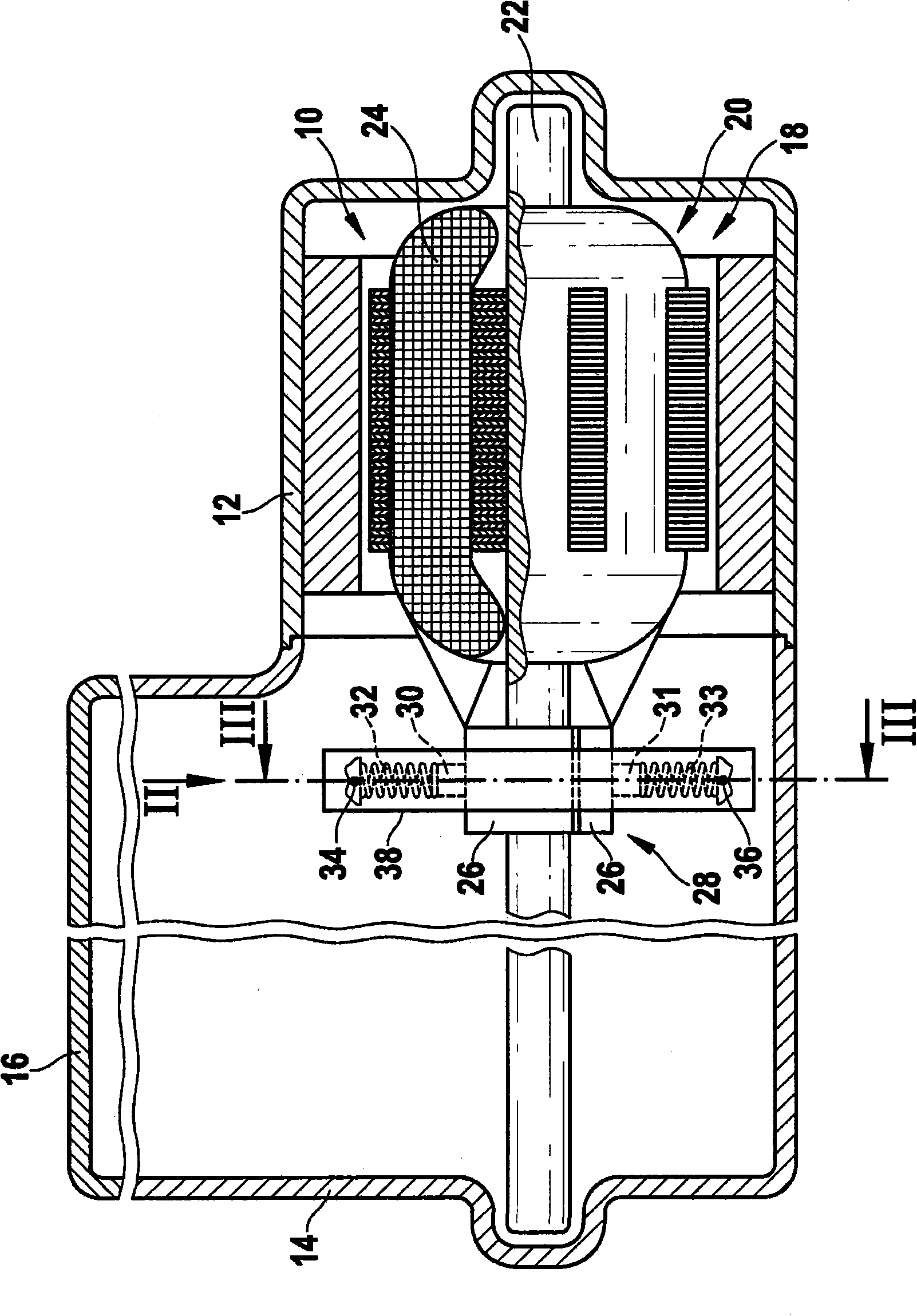
[0011] exist figure 1 10 denotes a schematically illustrated DC motor of the drive unit, which is arranged in a motor housing 12 to which a transmission housing 14 is flanged. The gear housing is closed by a gear cover 16 which, in the removed state, allows access for assembly purposes.

[0012] The DC motor 10 is designed as a commutator motor with a stator 18 and a rotor 20 whose shaft 22 extends as a drive shaft into the transmission housing 14 and is equipped with transmission components not shown. The rotor winding is indicated with 24 and is electrically conductively connected to laminations 26 of a commutator 28 which is likewise fastened on shaft 22 . Brushes 30 and 31 slide on the circumference of the commutator, said brushes being pressed radially against commutator 28 by symbolic brush springs 32 and 33 . The joints of the brush springs 32 and 33 are connected to the positive pole 34 and the negative pole 36 of the DC power supply.

[0013] In the exemplary embod...


PUM


Abstract

The invention relates to a drive unit, particularly a geared motor for windshield wipers, window lifting devices, or the like, of a motor vehicle, having a gear in a gear housing (14) and commutator motor disposed in a motor housing (12), comprising a stator (18) and a rotor (20), which together with a commutator (28) is disposed on a shaft (22) projecting into the gear housing (14). A brush holder (33) positioned in the gear housing (14) for at least two brushes (30, 31) adjacent to the commutator (28) under the pressure of double-journal brush springs (32, 33) is configured substantially ina U shape and has locking devices (46, 48) for supporting the brush springs (32, 33) in a positive fit on at least one side.

Description

technical field [0001] The invention relates to a drive unit according to the preambles of the independent claims, in particular a variable speed motor for a vehicle windshield wiper, window regulator or the like. Background technique [0002] A brush arrangement for an electric motor is known from WO 03 / 100920 A1, which has brush springs of the leaf spring type for pressing the brushes against the commutator, wherein the brush elements have electrical contacts on both sides. A support arm extending from the brush connects the brush spring with the brush holder through the support arm and elastically presses it onto the commutator. The arm of the brush spring has an angled section arranged offset with respect to the motor axis, which is screwed to the brush holder. Such elements require considerable effort not only in terms of production but also in terms of assembly. Contents of the invention [0003] Accordingly, the drive unit according to the invention having the fea...

Claims


Application Information

Patent Timeline
Patent Type & Authority Applications(China)
IPC IPC(8): H01R39/38
CPCH01R39/38
Inventor A·哈威戈尔斯特P·古贝尔
Owner ROBERT BOSCH GMBH
Why Eureka
Try Eureka