Touch panel and touch panel display device

A touch panel and display panel technology, which is applied to instruments, electrical digital data processing, and data processing input/output process, etc. Stress difference, the effect of improving uniformity

Inactive Publication Date: 2010-11-17
KYOCERA CORP
View PDF2 Cites 6 Cited by
  • Summary
  • Abstract
  • Description
  • Claims
  • Application Information

AI Technical Summary

Problems solved by technology

In the screen input display device of Patent Document 2, gaps or overlaps tend to occur at the interface between the conductive adhesive member and the adhesive tape, making it difficult to improve the uniformity of touch sensitivity.

Method used


Image

  • Touch panel and touch panel display device
  • Touch panel and touch panel display device
  • Touch panel and touch panel display device

Examples


Embodiment Construction

[0048] Hereinafter, a touch panel and a touch panel display device according to an embodiment of the present invention will be described with reference to the drawings.

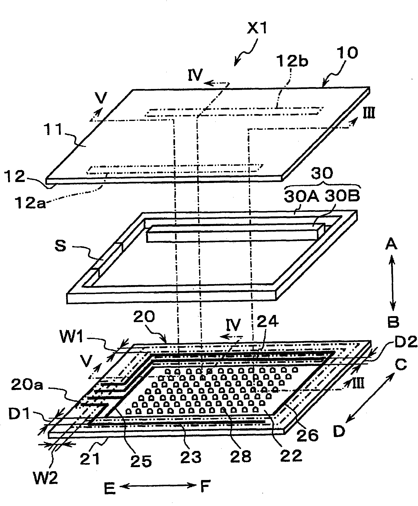
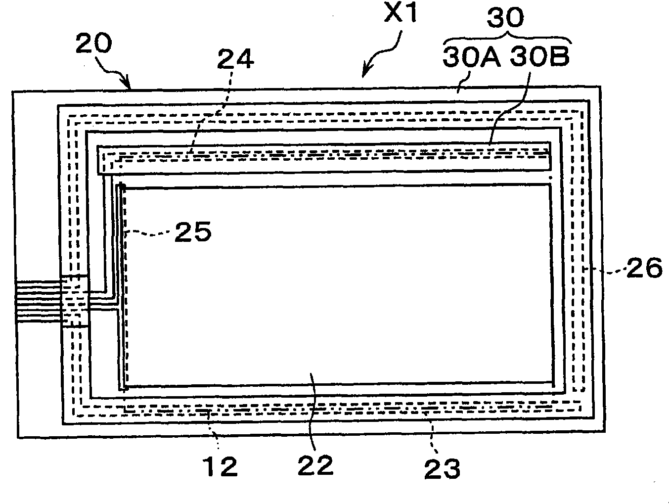
[0049] First, refer to figure 1 Moving to FIG. 6 , the touch panel X1 according to the first embodiment of the present invention will be described.

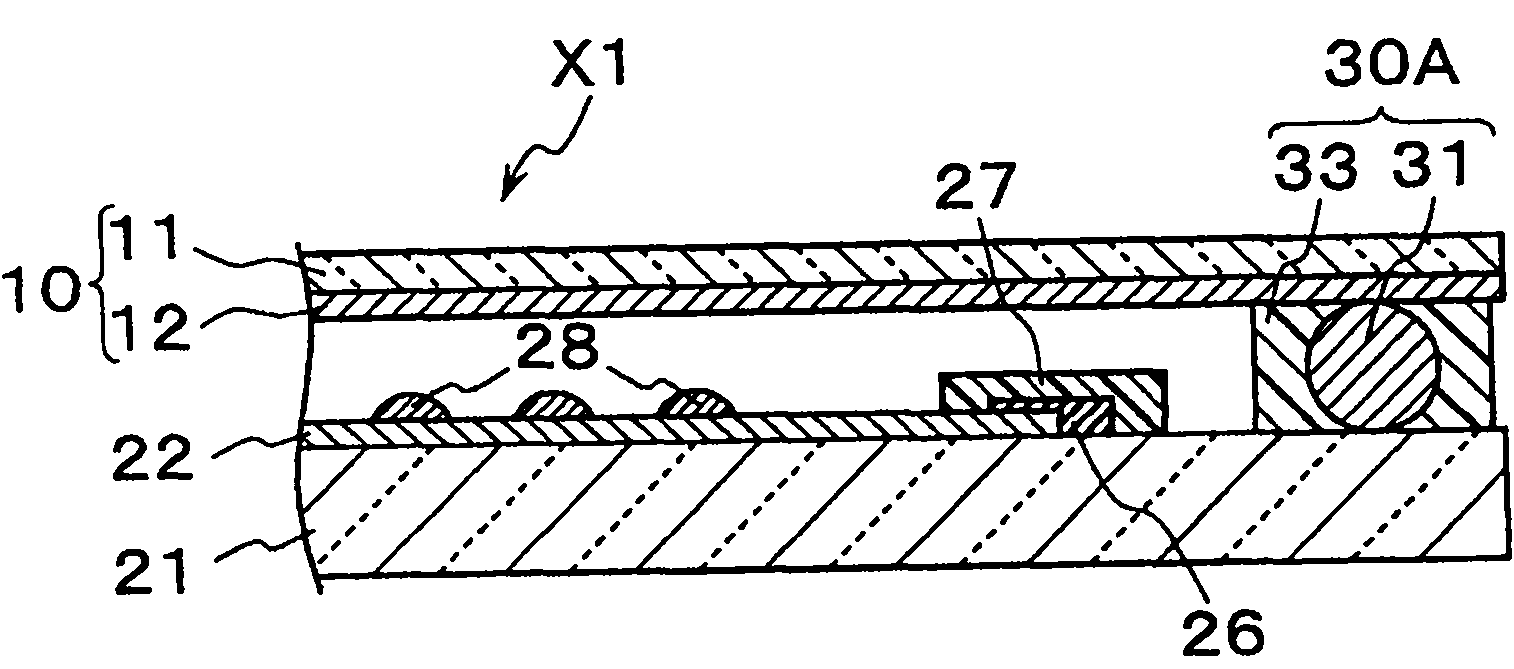
[0050] Such as figure 1 As shown, the touch panel X includes: a first base 10 , a second base 20 and a conductive adhesive member 30 .

[0051] The first base 10 includes a transparent insulating substrate 11 and a first resistive film 12 . In the present embodiment, the first base body 10 has flexibility as a whole, and its planar shape is substantially rectangular. The plan view shape of the first base body 10 is not limited to a substantially rectangular shape, and may be other shapes.

[0052] The transparent insulating base 11 is a member that supports the first resistive film 12 and has light transmission and electrical insulation in a direction inters...


PUM


Abstract

Disclosed is a touch panel (X1) comprising a first base (10), a second base (20) and a conductive connection member (30), wherein the first base (10) and the second base (20) are bonded with each other. The second base (20) has a wiring electrode (23) electrically connected to a first region (12a) of a first resistive film (12) and a wiring electrode (24) electrically connected to a second region (12b) of the first resistive film (12). The conductive connection member (30) has a first connection member (30A), which is so arranged as to surround a second resistive film (22) when viewed in plan and electrically connects the first region (12a) of the first resistive film (12) with the wiring electrode (23), and a second connection member (30B), which is arranged between the first connection member (30A) and the second resistive film (22) when viewed in plan and electrically connects the second region (12b) of the first resistive film (12) with the wiring electrode (24).

Description

technical field [0001] The present invention relates to a touch panel disposed on, for example, a display screen of a liquid crystal display or the like. The present invention further relates to a touch panel display device in which a touch panel is disposed on the display device. Background technique [0002] As a touch panel type display device, for example, there is a liquid crystal display device in which a touch panel that detects input coordinates by utilizing a change in resistance caused by a pressing operation is provided. [0003] The touch panel includes a first base and a second base, wherein the first base is formed by forming a transparent resistance film and wiring electrodes connected to the transparent resistance film on the lower surface of a flexible transparent insulating base, and the second base is formed by forming a transparent resistance film on the lower surface of a flexible transparent insulating base. The substrate is formed by forming a transpa...

Claims


Application Information

Patent Timeline
Patent Type & Authority Applications(China)
IPC IPC(8): G06F3/041G06F3/045
CPCG06F3/045
Inventor 野泽纯一
Owner KYOCERA CORP
Why Eureka
Try Eureka