Boiler pulse soot-blowing method and device thereof

A soot blowing device and boiler technology, applied in the field of boiler soot blowing, can solve the problems of complex equipment, wear and corrosion of pipes, high cost, etc., and achieve the effects of simple and reliable adjustment, wide application range and high work efficiency

Inactive Publication Date: 2011-10-26
周慧民
View PDF6 Cites 0 Cited by
  • Summary
  • Abstract
  • Description
  • Claims
  • Application Information

AI Technical Summary

Problems solved by technology

Such as steel ball soot blowing, the heating surface is severely worn, the steel balls cannot be completely recovered, and the accumulation in the flue makes the cost too high; steam soot blowing, compressed air soot blowing and gas pulse soot blowing are not effective for high cohesive ash accumulation; hydraulic removal Ash is effective for highly cohesive ash deposits, but like steam soot blowing, because it is a strong fluid flow, steam or water, which continuously scours the pipes, it is easy to wear and corrode the pipes; sonic soot blowing is effective for sparse and loose ash deposits It is effective, but the effect on dense and hard solid ash accumulation is very poor, and it cannot meet the requirements of soot blowing; the methods of steam soot blowing, hydraulic ash removal and compressed air soot blowing are relatively complicated, and steam soot blowing will consume strictly treated boilers. steam, which consumes a lot of energy

Method used


Image

  • Boiler pulse soot-blowing method and device thereof
  • Boiler pulse soot-blowing method and device thereof
  • Boiler pulse soot-blowing method and device thereof

Examples


Embodiment Construction

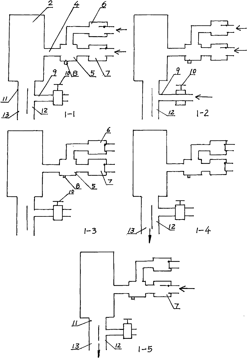
[0016] The invention will be further described below in conjunction with the accompanying drawings and embodiments.

[0017] figure 1 A schematic diagram of a pulse soot blowing method for a boiler is shown. 1-1 in the figure represents the first step of the method of the present invention. Enter the tank body 2, the second step of the method of the present invention in 1-2 among the figures, the water inlet valve 10 is opened, fill water in the water jet pipe 12 in the nozzle through the water inlet pipe 9, the third step of the present invention in 1-3 among the figures , when the mixture of combustible gas and air fills the tank and the water is filled into the jet pipe, close the water inlet valve 10, the air valve 7 and the gas valve 6 are in the closed state, at this time the ignition coil and the high-energy electric nozzle 8 are energized, and the mixing The igniter 5 ignites the combustible mixture, and the flame gas causes a strong deflagration in the tank body 2 th...


PUM


Abstract

The invention provides a boiler pulse soot-blowing method, which comprises the following steps: filling mixed gas of inflammable gas and air into a tank body, and then filling water into an outlet pipe and a nozzle connected with the tank body; igniting the inflammable mixed gas, and then spraying the detonated gas along with water out of the nozzle; filling air into the tank body, the outlet pipe and the nozzle, and then eliminating waste gas; and finally repeating the above steps to form a water-containing pulse shock wave at the outlet of the nozzle for carrying out boiler soot-blowing. The invention further provides a boiler pulse soot-blowing device for realizing the method, and the boiler pulse soot-blowing device is composed of a gas pipeline and a metering input distributor, an air pipeline and a metering input distributor, a water supply pipeline and a metering input distributor, a shock wave generator, a nozzle, a water inlet pipe and a water inlet valve, wherein the nozzle is equipped with a water jetting pipe communicated with the water inlet pipe, and the water inlet pipe is equipped with the water inlet valve. The boiler pulse soot-blowing device of the invention has simple structure, wide application range, convenient and flexible operation and long service life.

Description

technical field [0001] The invention relates to boiler soot blowing technology, in particular to a boiler pulse soot blowing method and device. Background technique [0002] It is unavoidable for various boilers to have ash on the heating area during the working process. These ash deposits on the heating surface will weaken the heat exchange between the flue gas and the working medium to varying degrees, increase the resistance of the flue gas, increase the temperature of the exhaust gas, reduce the thermal efficiency of the boiler, and affect the normal operation of the boiler in severe cases. For a long time, the problem of soot blowing on the heating surface of the boiler has always been one of the problems that have received special attention during the operation of the boiler. Over the years, people have used many soot blowing methods to soot blow the heating surface without stopping the furnace: such as small steel ball soot blowing, steam soot blowing, hydraulic soot...

Claims


Application Information

Patent Timeline
Patent Type & Authority Patents(China)
IPC IPC(8): F23J1/00F23J3/00
Inventor 周慧民
Owner 周慧民
Why Eureka
Try Eureka