Adjustable sub-lead spacer

A spacer and wire technology, which is applied in the direction of the device for maintaining the distance between parallel conductors and the mechanical vibration attenuation device, etc., can solve the problems of affecting the visual aesthetics of the jumper, easy to damage the jumper spacer, and the blind area of ​​​​adjustment, etc., to achieve a compact structure , Convenient error, wide application range

Active Publication Date: 2010-12-29
CHINA ELECTRIC POWER RES INST +1
View PDF3 Cites 14 Cited by
  • Summary
  • Abstract
  • Description
  • Claims
  • Application Information

AI Technical Summary

Problems solved by technology

The structure of the jumper spacer in the prior art is usually a fixed-length split pitch, and it is difficult to realize that the split pitch of each sub-conductor is a fixed value during the installation of the jumper. If a fixed-length split sub-wire spacer is used, not only It will affect the visual aesthetics of the jumper, and it will cause stress concentration and easily damage the jumper spacer
[0004] The Chinese utility model patent with the notification number CN201243187Y discloses an adjustable conductor interphase spacer. An adjustment plate and a connecting plate are arranged between the spacer and the insulator end hardware. By adjusting the fixed position of the adjustment hole on the adjustment plate, the Adapt to and make up for the error of wire sag installation, but because this kind of spacer adopts the structure of the adjustment hole, there will still be blind spots in the adjustment, so when it is necessary to fine-tune the phase spacing of the wires, the spacer is still not competent

Method used


Image

  • Adjustable sub-lead spacer
  • Adjustable sub-lead spacer
  • Adjustable sub-lead spacer

Examples


Embodiment Construction

[0024] The wire jumper spacer of the present invention will be further described in detail below in conjunction with the accompanying drawings.

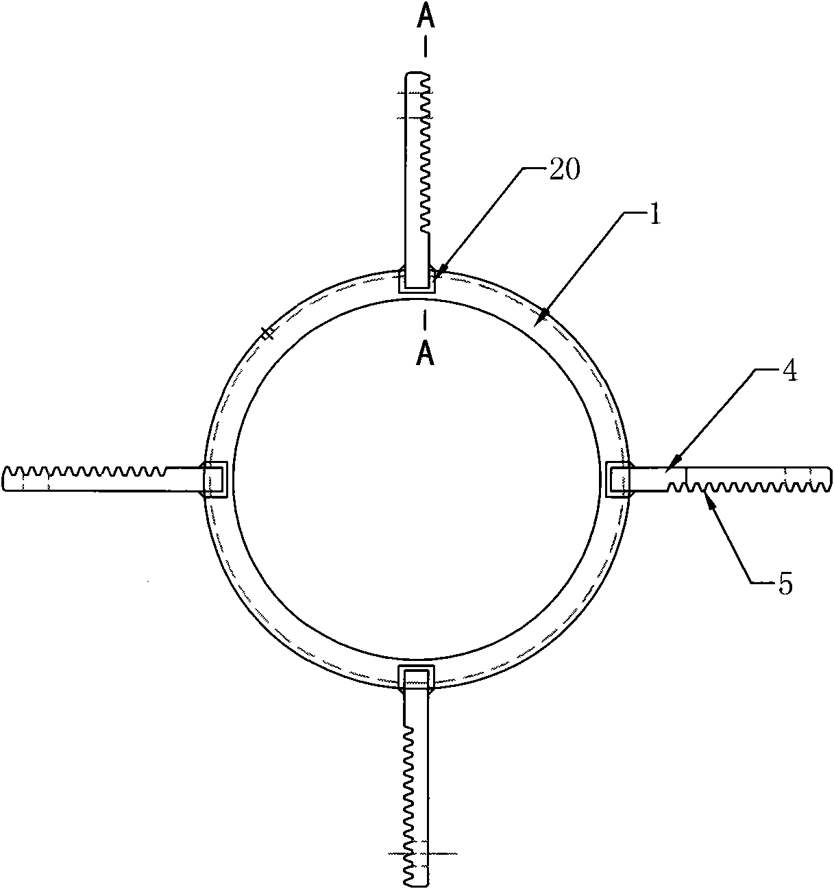
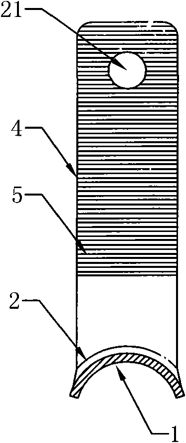
[0025] Such as figure 1 As shown, the frame 1 is a ring-shaped structure, and four inner grooves 20 are evenly distributed on its outer circumference, and a connecting plate 4 is fixedly connected in each inner groove 20, as figure 2 As shown, the connecting plate 4 is a bar-shaped structure, a rack 5 is provided on one side thereof and a mounting hole 21 is provided on the upper part thereof.

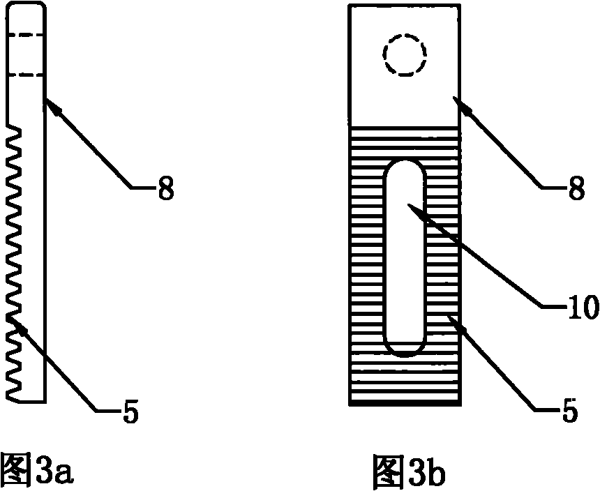
[0026] Such as image 3 As shown in a and 3b, the adjustment plate 8 is a bar-shaped structure, and a rack 5 is also provided on one side of the adjustment plate, and a long positioning hole 10 is provided in the bottom of the adjustment plate. The length of the positioning hole is preferably set as: greater than or equal to 1 / 2 the length of the adjustment plate 8 and less than the length of the adjustment plate 8.

[0027] The design of...


PUM


Abstract

The invention relates to a spacer for transmission line in the air, in particular to an adjustable sub-lead spacer, comprising a frame, wire clamp bodies and wire clamp cover boards; the frame is ring-shaped, binding plates are uniformly distributed on the outer circumference of the frame; the front part of the wire clamp body and the front part of the wire clamp cover plate are connected together through a connecting piece to form a hollow cavity for clamping the sub-lead; an adjusting plate is connected between two convex lugs at the rear end of the wire clamp body; the binding plate and the adjusting plate are provided with the racks on the sides opposite to each other; and the distance between the sub-leads is adjusted by changing the engaging position of the racks on the binding plate and the adjusting plate. The spacer has the advantages of compact structure, convenient installation, wide application range, and the like, thereby being capable of conveniently compensating the lead arc vertical installation error, and also being capable of adjusting the distance between the sub-leads in fine tuning mode or coarse tuning mode; and the distance is adjusted without blind region to realize stepless adjustment of the distance between the sub-leads.

Description

technical field [0001] The invention relates to a spacer bar for an overhead power transmission line, in particular to an adjustable sub-conductor spacer bar. Background technique [0002] Ice-coated galloping of overhead transmission line conductors has always been a thorny problem that seriously threatens the safe and stable operation of transmission lines. When the ice-covered conductor dances, the conductors of each phase will vibrate irregularly with different waveforms and different phases, and it is very easy to cause phase-to-phase or phase-to-ground air breakdown flashover (especially for compact transmission lines). Vicious accidents of damage to line fittings, ground wires, pole towers, etc., galloping have brought great harm to the safe operation of transmission lines. [0003] The spacer bar is one of the anti-flying devices to prevent wire galloping. Its anti-dancing principle is to mechanically connect the wires of each phase so that they are mutually restra...

Claims


Application Information

Patent Timeline
Patent Type & Authority Applications(China)
IPC IPC(8): H02G7/12H02G7/14
Inventor 牛海军朱宽军刘彬李新民
Owner CHINA ELECTRIC POWER RES INST
Why Eureka
Try Eureka