Vibration measurement equipment for rail and measurement system using same

A technology of vibration measurement and rail, applied in the field of measurement system, to achieve the effect of convenient installation

Active Publication Date: 2012-08-08
TSINGHUA UNIV +1
View PDF0 Cites 2 Cited by
  • Summary
  • Abstract
  • Description
  • Claims
  • Application Information

AI Technical Summary

Problems solved by technology

At present, there is no detection equipment suitable for detecting falling rocks from high mountains and dangerous cliffs that destroy railroad tracks on the market

Method used


Image

  • Vibration measurement equipment for rail and measurement system using same
  • Vibration measurement equipment for rail and measurement system using same
  • Vibration measurement equipment for rail and measurement system using same

Examples


no. 1 example

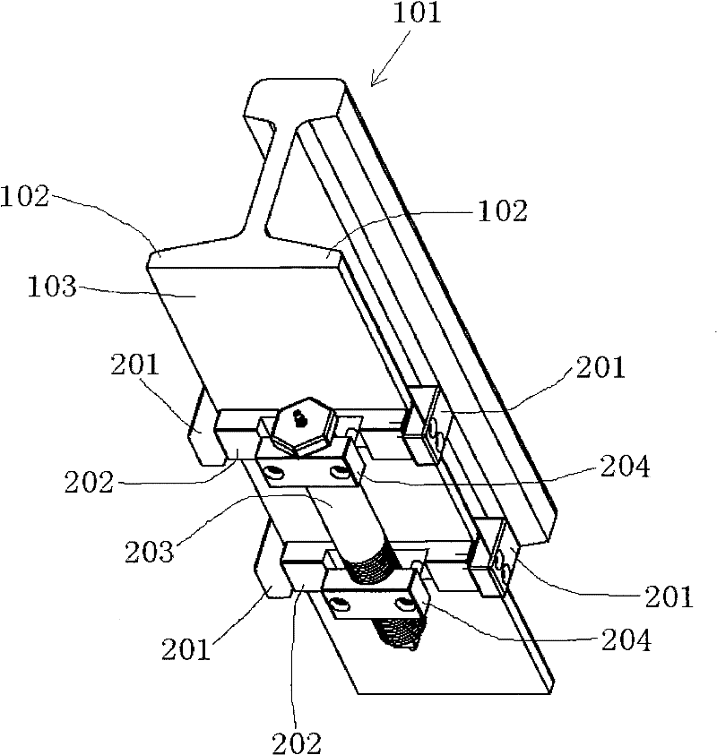
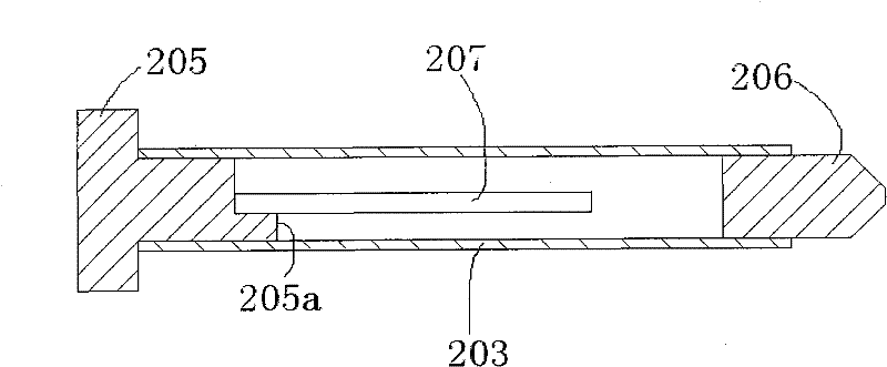
[0015] figure 1 and figure 2 A first embodiment of the vibration measuring device for railroad rails of the present invention is shown. figure 1 It is a schematic diagram of the three-dimensional structure of the first embodiment of the rail vibration measuring device of the present invention; figure 2 yes figure 1 Schematic diagram of the structure of the protection tube of the vibration measurement equipment for railway rails shown.

[0016] Such as figure 1 As shown, the vibration measurement equipment for rail includes a protection tube 203 with a vibration sensor 207 installed inside and two sets of claw fixing components located at both ends of the protection tube 203 .

[0017] Such as figure 1 As shown, the protection tube 203 is fixedly installed on the bottom 103 of the rail 101 through two sets of claw fixing components, and is substantially parallel to the longitudinal direction of the rail 101 . It should be noted that the protection tube 203 can also be a...

no. 2 example

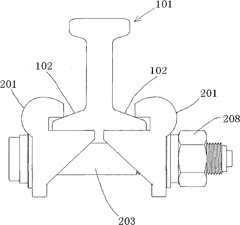
[0024] image 3 A schematic structural view showing a second embodiment of the rail vibration measuring device of the present invention.

[0025] Such as image 3 As shown, the protective tube 203 is fixed substantially parallel to the transverse direction of the rail 101 . It should be noted that the protective pipe 203 may also form an inclined angle with the transverse direction of the rail 101 .

[0026] Such as image 3 As shown, a pair of holding claws 201, 201 are respectively grasped on the flanges 102 on both sides of the lower part of the rail 101, and the pair of holding claws 201, 201 are transversely opposite to each other. Two ends of the protection tube 203 are respectively supported and fixed on a pair of claws 201 , 201 . Preferably, the protection tube 203 is fastened to the pair of claws 201 , 201 by using a lock nut 208 provided at one end of the protection tube 203 .

[0027] In this embodiment, the holding claw device only includes a pair of holding ...


PUM


Abstract

The invention discloses vibration measurement equipment for a rail, comprising a vibration sensor and a claw holding device, wherein the vibration sensor is installed in a protection box; and the claw holding device is held on flanges at two sides of the lower part of the rail for fixedly installing the protection box on the bottom of the rail. Compared with the prior art, the vibration measurement equipment adopts the claw holding device to directly fix the vibration sensor on the rail. The installation mode is convenient, does not affect normal driving of a train and does not affect drivingsafety. The whole vibration sensor is sealed in the protection box, thus the vibration measurement equipment is suitable for outdoors and can prevent water and moisture.

Description

technical field [0001] The present invention relates to a vibration measurement device for a rail and a measurement system using the vibration measurement device. Background technique [0002] Strong winds, heavy rains, earthquakes, geological movements, etc. will lead to landslides. Since the railways in mountainous areas are generally winding railways or mountain-crossing railways, sometimes huge stones will fall directly from high places onto the railway tracks, sleepers and ballast shoulders. Smashing rails, sleepers or ballast shoulders will seriously affect the safety of railway traffic. For China, where earthquakes and other geological disasters occur frequently, this problem is even more prominent. At present, there is no detection equipment suitable for detecting railroad tracks destroyed by falling rocks from high mountains and dangerous cliffs on the market. Contents of the invention [0003] Therefore, the purpose of the present invention is to provide a meas...

Claims


Application Information

Patent Timeline
Patent Type & Authority Patents(China)
IPC IPC(8): G01H9/00
Inventor 陈志强李元景徐惠康温海宁钱鸿治王治强
Owner TSINGHUA UNIV
Why Eureka
Try Eureka