Detection and amplification device for micro current

An amplifying device and micro-current technology, which is applied in the direction of measuring devices, DC-coupled DC amplifiers, differential amplifiers, etc., can solve the problems of unusable amplifiers, difficult to eliminate drift, frequent micro-currents, etc., and achieve simple implementation and adjustable magnification , easy-to-achieve effects

Active Publication Date: 2013-06-26
HISENSE HOME APPLIANCES GRP CO LTD +1
View PDF3 Cites 0 Cited by
  • Summary
  • Abstract
  • Description
  • Claims
  • Application Information

AI Technical Summary

Problems solved by technology

[0002] Micro-currents are becoming more and more frequent in daily detection and processing, which requires the detection and amplification of micro-currents. But ordinary amplifiers can no longer be used because their input offset voltage is above hundreds of microvolts. It is enough to drown the signal. Even if the offset The voltage can be adjusted to zero, but the drift is difficult to eliminate, so a special circuit is required for the detection and amplification of the micro current

Method used


Image

  • Detection and amplification device for micro current
  • Detection and amplification device for micro current
  • Detection and amplification device for micro current

Examples


Embodiment Construction

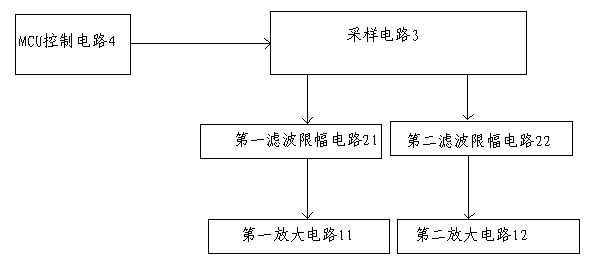
[0015] see figure 1 , a block diagram of the structure of the micro-current detection and amplification device of the present invention, including a sampling circuit 3, an MCU control circuit 4 that controls the magnitude of the sampling voltage, and an amplifying circuit that amplifies the sampling voltage output by the sampling circuit, wherein the sampling circuit and the amplifying circuit are also connected. A filtering and limiting circuit is connected. The amplifying circuit includes a first amplifying circuit 11 and a second amplifying circuit 12. The filtering and limiting circuit includes a first filtering and limiting circuit 21 and a second filtering and limiting circuit 22. The MCU control circuit 4 controls the sampling circuit. The sampling voltage of the first channel output by 3 is limited and filtered by the first filtering and limiting circuit 21, and then input to the first amplifying circuit 11 for amplification; The circuit 22 is limited and filtered, and...


PUM


Abstract

The invention discloses a detection and amplification device for micro current, comprising a sampling circuit, an MCU (Micro Control Unit) control circuit and an amplification circuit, wherein the MCU control circuit controls sampling voltage; the amplification circuit amplifies the sampling voltage output by the sampling circuit; a filtering amplitude limiting circuit is connected between the sampling circuit and the amplification circuit; the amplification circuit comprises a first amplification circuit and a second amplification circuit; the filtering amplitude limiting circuit comprises afirst filtering amplitude limiting circuit and a second filtering amplitude limiting circuit; the MCU control circuit controls the first path of sampling voltage output by the sampling circuit to be filtered by the first filtering amplitude limiting circuit, and the first path of sampling voltage is input into a first path of amplification circuit for amplifying; and the MCU control circuit controls the second path of sampling voltage output by the sampling circuit to be filtered by the second filtering amplitude limiting circuit, and then, the second path of sampling voltage is input to the second amplification circuit for amplifying. The detection and amplification device has the advantages of accurate sampling, adjustable amplification multiple, simple circuit, reasonable design, strong practicality, simplified use and operation and strong anti-interference performance, and is simple and easy to realize.

Description

technical field [0001] The invention relates to a micro-current detection and amplification device. technical background [0002] Micro-currents are becoming more and more frequent in daily detection processing, which requires detection and amplification of micro-currents. But ordinary amplifiers can no longer be used because their input offset voltages are above hundreds of microvolts. It is enough to drown the signal. Even if the offset The voltage can be adjusted to zero, but the drift is difficult to eliminate, so a special circuit is required for the detection and amplification of micro-current. SUMMARY OF THE INVENTION [0003] In order to overcome the above technical defects, the present invention provides a micro-current detection and amplification device with simple circuit, reasonable design, strong practicability, simplified operation and strong anti-interference. [0004] In order to achieve the above purpose, the specific technical solutions are: [0005] Th...

Claims


Application Information

Patent Timeline
Patent Type & Authority Patents(China)
IPC IPC(8): H03F3/45G01R15/00G01R19/00
Inventor 任艳芳陈坚波吕根贵
Owner HISENSE HOME APPLIANCES GRP CO LTD
Why Eureka
Try Eureka