Cable clamping device of electric power circuit fault indicator

A fault indicator and power line technology, which is applied to measuring devices, measuring device casings, instruments, etc., can solve the problems of high price and complicated structure of the cable clamping device, and achieve simple installation and production, saving magnetic conductive materials, and reliable wire pressing. Effect

Active Publication Date: 2011-08-03
FUJIAN HONGKE ELECTRIC POWER SCI & TECH CO LTD
View PDF5 Cites 5 Cited by
  • Summary
  • Abstract
  • Description
  • Claims
  • Application Information

AI Technical Summary

Problems solved by technology

[0003] The purpose of the present invention is to overcome the disadvantages of complex structure and high price of the clamping device, and provide a clamping device for power line fault indicators with low cost, convenient installation and reasonable structure layout

Method used


Image

  • Cable clamping device of electric power circuit fault indicator
  • Cable clamping device of electric power circuit fault indicator
  • Cable clamping device of electric power circuit fault indicator

Examples


Embodiment 1

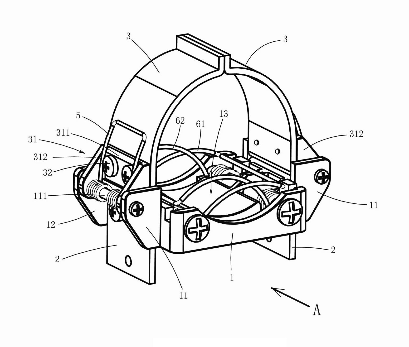
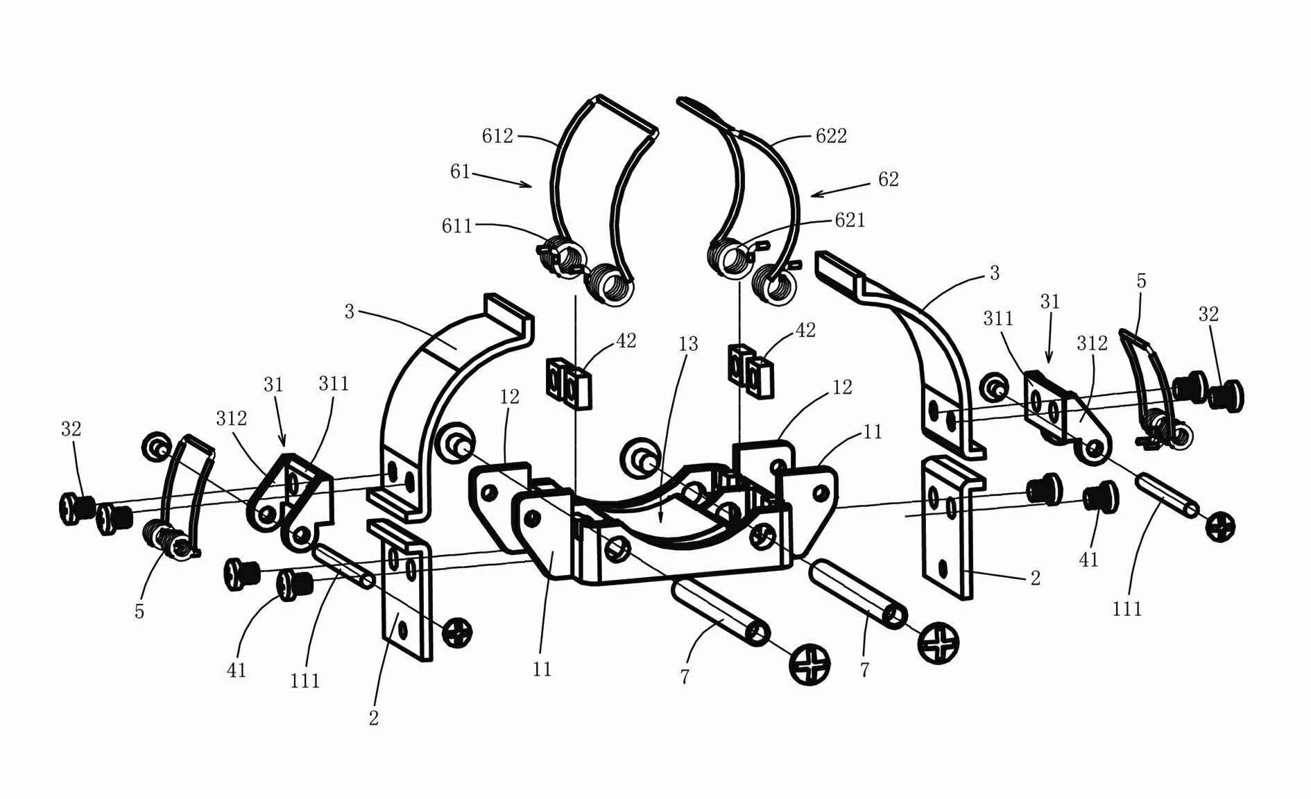
[0028] refer to figure 1 , figure 2 and combine Figure 4 to Figure 7 . The clamping device of the power line fault indicator includes an integrally formed base 1, uprights 2 installed symmetrically on both sides of the base 1, and two openable and closed magnetic plates that are relatively arranged on both sides of the base 1 through pivoting seats 31 3 and a reset mechanism that drives the two magnetically conductive plates 2 to close together, and the base 1 is equipped with a crimping device for crimping the working cable.

[0029] refer to figure 1 , figure 2 and combine Figure 4 to Figure 7 . The above-mentioned base 1 is made of plastic material, and is an integrated base. The two side walls of the base 1 are correspondingly provided with a pair of ear plates 11, 12 integrally formed with the base 1, pin holes are opened on the ear plates 11, 12, and a pin shaft 111 is pierced between the two ear plates 11, 12 . The magnetically conductive plate 3 is an arc-...

Embodiment 2

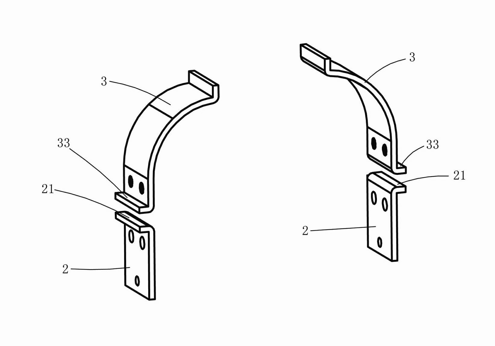
[0035] refer to Figure 9 . The difference between this embodiment and the first embodiment is that the width of the magnetic guide plate 3 is smaller than the width of the connecting plate 311 of the pivotal seat, and the two sides of the connection surface of the connecting plate 311 opposite to the magnetic guide plate 3 are symmetrically provided with positioning plates 313, The distance between the two positioning plates 3 is equivalent to the width of the magnetic conducting plate 3 , and the lower end of the magnetic conducting plate 3 is fixedly fitted between the two positioning plates 313 . Because the lower end of the magnetic guide plate 3 fits between the two positioning plates 313, the left and right deflection of the magnetic guide plate 3 is limited by the two positioning plates 313, so that the magnetic guide plate 3 is firmly connected with the pivot seat 31, ensuring that the magnetic guide plate 3 work reliably. The rest of the structure is the same as th...


PUM


Abstract

The invention discloses a cable clamping device of an electric power circuit fault indicator. The device comprises a base, two vertical columns, two magnetic conduction plates capable of opening and closing and a resetting mechanism, wherein the vertical columns are oppositely arranged on the two sides of the base; the resetting mechanism is used for driving the magnetic conduction plates to be closed and pressed against each other; and a cable pressing device for pressing a working cable is arranged on the base. The device is characterized in that: the base is an integrated integral type base; the vertical columns are fixedly arranged on the two sides of the base; the magnetic conduction plates are arc-shaped panels; the lower end parts of the two magnetic conduction plates are fixedly connected with a pivoting seat respectively; pivoting seats are hinged on the base; the magnetic conduction plates are rotatably arranged on the corresponding part of the base through corresponding pivoting seats; the lower end part of each magnetic conduction plate is fixedly connected with one pivoting seat; two pairs of lug plates which are integrated with the base are correspondingly arranged on the two sides of the base; a pin shaft is inserted into the space between every two lug plates; and the pin shaft between the two lug plates are rotatably inserted into the pivoting seat. The lower ends of the magnetic conduction plates which are made of expensive materials are not required to be molded with pin seats, so that a large number of magnetic conduction materials are saved, and the cost is reduced; and the base is integrated, so that the device has high structural integrity and a reasonable design and is easy to mount and manufacture.

Description

Technical field [0001] The invention involving circuit fault detection instruments are specifically a card line device of the power line fault indicator. Background technique [0002] The open number CN201133927Y revealed the card line structure of a fault indicator, including the base and the pressure line device installed on the base, which is set on the base.In the open state, a part of the pressure line device is located that part of the trigger device is suitable for contact with the external cable phase. The external cable can promote the trigger device.The base of this card line structure includes the upper and lower pads between the two columns between the two intervals, the activity connection between the two columns, and the upper end of the column and the moving plate.Connect the corresponding column; the shortcomings of this structure are: the pillars and dynamic boards made of magnetic materials are high, and the sales seats are set on the columns and dynamic boards ...

Claims


Application Information

Patent Timeline
Patent Type & Authority Applications(China)
IPC IPC(8): F16M13/02G01R1/04G01R31/02
Inventor 赖安定林党养李文锦
Owner FUJIAN HONGKE ELECTRIC POWER SCI & TECH CO LTD
Why Eureka
Try Eureka